
Operation Manual


5
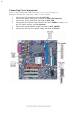
Introducing the Motherboard
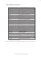
Table of Motherboard Components
1 CPU Socket LGA775 socket for Pentium 4/Celeron CPUs
2 CPU_FAN CPU cooling fan connector
4 ATX_POWER Standard 24-pin ATX power connector
LABEL COMPONENT
7 IDE1 Primary IDE channel
5 IDE2 Secondary IDE channel
3 DIMM1~DIMM2 184-pin DDR SDRAM slots
25 PCIEX16 PCI Express x16 slot for graphic card
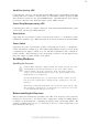
This concludes Chapter 1. The next chapter explains how to install the motherboard.
27 ATX12V Auxiliary 4-pin power connector
15 USB3~4 Front Panel USB headers
14 SATA1~SATA4 FourSerial ATA connectors(SiS965 supports )
22 SPDIFO1 SPDIF out header
11 PANEL1 Front panel switch/LED header
6 FDD Floppy diskette drive connector
18 BIOS_WP BIOS Flash Protect jumper
24 PCI1~PCI3 Three 32-bit add-on card slots
23 CD_IN Analog audio input connector
10 WOL Wake on LAN wakeup connector
16 PWR_FAN* Power cooling fan connector
9 WOM Wake on Modem wakeup connector
12 SJ1* Single-colored LED header
19 COM2 Onboard serial port connector
13 IRDA Infrared header
8 CLR_CMOS Clear CMOS jumper
21 AUX_IN Auxiliary In connector
26 SYS_FAN System cooling fan connector
17 1394A2* Onboard IEEE 1394a connector
“*” stands for optional components.
20 AUDIO1 Front panel audio header