
User Manual

9
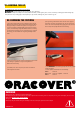
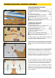
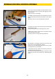
2) Fixer les câbles aller-retour sur les chapes comme
montré; un bout de gaine thermo autour de l’embout
assurera un montage plus «propre».
H Attach the pull-pull cables on the clevises as shown;
a piece of shrinking tube around the coupler will en-
sure a «cleaner» assembly.
3) Visser le servo de direction dans son logement et
y raccorder les câbles de direction sur un palonnier
adéquat; dans notre cas, palonnier double Gabriel
#146992806F (non fourni).
H Attach the rudder servo into its housing and connect
the rudder cables to a suitable servo arm; in our case,
Gabriel Double Rudder Arm #146992806F (not sup-
plied).
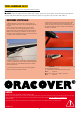
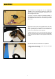
1) Dégager l’emplacement du guignol et le coller en
position.
!Attention à la symétrie par rapport au volet!
H Clear the location of the horn and gllue it in position.
! Pay attention to the symmetry with respect to the
rudder post!
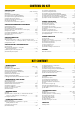
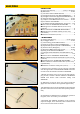
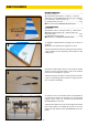
DIRECTION/RUDDER
PIECES DIRECTION
(A) Volet de dérive ........................................................ 1
(B) Commande de direction > câble (1) + chape à
rotule avec visserie M3x14mm et écrou (4) + embout
pour câble (4) + tubes à sertir (4) ......................... 1 set
(C) Guignol bre de verre ....................................... 1 set
l Servo direction TOPMODEL HV48010MG .............. 1
H RUDDER PARTS
(A) Rudder ..................................................................... 1
(B) Rudder control > Pull-pull cable (1) + Ball clevis
M3x14mm with screws (4) + cable coupler (4) +
Press tting (4) ........................................................ 1 set
(C) Fiberglass control horn .................................... 1 set
l Rudder servo TOPMODEL HV48010MG ................. 1
A
B
C
1
2
3