
installation manual


8
PANEL RADIATORS ECOSTYLE
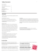
Radiator Connection Fittings
Ecostyle
4
3
··
2
DIVERTER VALVES
ISOLATION VALVES
TOWEL BAR VALVES
PIPE CONNECTIONS - (SOLD PER PAIR)
RV-301241 STAIGHT DIVERTING VALVE
RV-301341 ANGLED DIVERTING VALVE
NOTES: ADJUSTABLE BY-PASS FROM 30 - 50 %
THERMOSTATIC CONTROL
RV-301040 STAIGHT ISOLATING VALVE
RV-301140 ANGLED ISOLATION VALVE
RV-200000 THERMOSTATIC CONTROL HEAD
RV-338452 ANGLED THERMOSTATIC VALVE
RV-339452 STRAIGHT THERMOSTATIC VALVE
RV-342452 ANGLED SHUT OFF
RV-343452 STRAIGHT SHUT OFF
RV-681503A 3/8” PEX COMPRESSION FITTING
RV-681524 1/2” PEX COMPRESSION FITTING
RV-681555 5/8” PEX COMPRESSION FITTING
RV-437516 1/2“ COPPER COMPRESSION FITTING
RV-NA10262 1/2” COPPER SWEAT FITTING
RV-940451 RADIATOR ADAPTER (MUST BE USED FOR DIRECT
PIPE CONNECTION TO RADIATOR - NO DIVERTER OR ISOLATION VALVE)
Z
A
A
Z
Z
A
A
Z
1
1
2
3
2
3
5
4
4
5
6
7
6
7
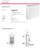
Fig. 4
6
5
4
3
2
1
6
5
4
3
2
1
6
5
4
3
2
1
Flow Seng: 6
Maximum flow
allowed through
radiator
Flow Seng: 3
Half flow allowed
through radiator
Flow Seng: 1
Minimum flow
allowed through
radiator
Each Ecostyle radiator is supplied with a adjustable valve body. Each valve
body is fied with a factory installed manual adjustment cover (Fig. 1). By
turning the cover clockwise water flow to the radiator is reduced. By turning
the cover counter clockwise water flow to the radiator is increased. If the
cover is removed completely (Fig. 2), the valve will be in the full open posion.
Each valve is also equipped with a flow limiter adjustment. It will control how
much water is allowed through the radiator at the full open cover posion. It is
adjusted by turning the black plasc segmen of the valve. The adjustment is
labeled with the numbers 1 through 6. 1 being the least amount of flow and 6
being the maximum amount of flow. The indicator mark on the brass secon
of the valve indicates the seng of the valve. Fig. 3 shows examples of three
different sengs.
A termostac head can also be mounted to the valve body to allow automac
adjustment of the valve according to room temperature. To fit the
thermostad head, simply remove the adjustment cover completely exposing
the valve body. Place the collar of the thermostac head over the valve body
(Fig 4). Thread the collar of the thermostac head onto the valve body unl
ght (Fig. 5). Set the termostac head according to the manufacturers
instrucons for desired room temperature.
Fig. 5
Fig. 1
Fig. 2
Fig. 3
Thermostatic Valve Adjustment