How to maintain and operate your Demand Controlled Water Softener DO NOT RETURN TO STORE If you have questions or concerns when installing, operating or maintaining your softener, visit www.leaumiraclewater.ca or call our toll free number: 1-800-356-7851 Systems tested and certified by NSF International against NSF/ANSI Standard 44 for hardness reduction and efficiency. Systems tested and certified by the Water Quality Association against CSA B483.1.
Table of Contents Unpacking and Inspection . . . . . . . . . . . . . . . . . . . . . . . . . . . . . . . . . . . . . . . . . . . . . . . . . . . . . . . . . . . . . . .3 Dimensions/Specifications . . . . . . . . . . . . . . . . . . . . . . . . . . . . . . . . . . . . . . . . . . . . . . . . . . . . . . . . . . . . . . .4 Wiring Schematic . . . . . . . . . . . . . . . . . . . . . . . . . . . . . . . . . . . . . . . . . . . . . . . . . . . . . . . . . . . . . . . . . . . . . . .
Unpacking and Inspection The parts required to assemble and install the unit are included in a parts bag. Thoroughly check the unit for possible shipping damage and parts loss. Also inspect and note any damage to the shipping carton. Remove and discard (RECYCLE) all packing materials. To avoid loss of small parts, we suggest you keep the small parts in the parts bag until you are ready to use them.
Dimensions/ Specifications MODEL MW-30 MW-40 NOMINAL RESIN TANK SIZE 9” Dia. x 35” 9” Dia.
Miscellaneous Service Information DESIGN SPECIFICATION FILL CYCLE 1 FLOW BRINE CYCLE 2 FLOW BRINE RINSE CYCLE 2 FLOW BACKWASH CYCLE (MAX.) 2 FLOW FAST RINSE CYCLE (MAX.) 2 FLOW MW-30 .3 gpm .22 gpm .15 gpm 2.0 gpm 2.0 gpm MW-40 .3 gpm .22 gpm .15 gpm 2.0 gpm 2.0 gpm 1 gallon per minute flow to brine tank 2 gallon per minute flow to drain Salt Storage Capacity MW-30 - 150 lbs. MW-40 - 175 lbs. Product Specifications Rated Service Flow Rate (gpm) Amount of High Capacity Ion Exchange Resin (cu. ft.
Safety Guides Follow the installation instructions carefully. (Failure to install the unit properly voids the warranty.) Before you begin installation, read this entire manual. Then, obtain all the materials and tools you will need to make the installation. Check local plumbing and electrical codes. The installation must conform to them. Use only lead-free solder and flux for all sweat-solder connections, as required by state and federal codes. Use care when handling the unit.
ed. A water softener removes the hardness minerals to eliminate these problems, and others. Sodium Information: Water softeners using sodium chloride (salt) for regeneration and add sodium to the water. Persons on sodium restricted diets should consider the added sodium as part of their overall intake. 2. IRON in water is measured in parts per million (ppm). The total* ppm of iron, and type or types*, is determined by chemical analysis.
Assembly 1. Miracle Water models are factory assembled. During installation, remove the Salt Hole Cover. Set aside to prevent damage. Check the brinewell to be sure it is secured and vertical (see Figure 1). Slide Faceplate Cover forward to expose back valve assembly. 2. Lift the brine valve out of the brinewell. Be sure the float stem is parallel to stand tube so seals will seat properly during operation. Replace the brine valve in the brinewell bottom and install the Brinewell Cover. 3.
Planning Installation Inlet - Outlet Plumbing Options • ALWAYS INSTALL either a single bypass valve (included) or a 3 valve bypass system (not included). Bypass valves allow you to turn off water to the softener for repairs if needed, but still have water in house pipes. • Use 3/4” (minimum) pipe and fittings. • Use sweat copper... or, threaded pipe... or, PVC plastic pipe... or, other approved plumbing.
Other Requirements • A 120V-60Hz, grounded electrical outlet (continuously ‘‘live’’) is needed within 10’ of the unit. • A drain is needed for regeneration discharge water. A floor drain, close to the unit, is preferred. A laundry tub, standpipe, etc., are other drain options.
*VALVE DRAIN OPTIONS: Flexible drain hose is not allowed in all localities (check your plumbing codes). For a rigid valve drain run, cut the barbed section off the drain fitting for access to the 1/4” pipe threads. Then plumb a rigid drain as needed (see Figure 4). Select Installation Location Consider all of the following when selecting an installation location for the unit.
Installation Step 1. Turn Off Water Supply 1. Close the main water supply valve, near the well pump or water meter. 2. Shut off the electric or fuel supply to the water heater. 3. Open all faucets to drain all water from the house pipes. Step 2. Move the Unit into Place Move the unit into installation position. Set it on a solid, smooth and level surface. If needed, place the unit on a section of plywood, a minimum of 3/4” thick. Then, shim under the plywood to level the unit, see Figure7.
Step 3. Assemble Inlet and Outlet Plumbing Measure, cut, and loosely assemble pipe and fittings from the main water pipe to the inlet and outlet ports of the valve. Be sure hard water supply pipe goes to the valve inlet side. NOTE: Inlet and outlet are marked on the valve. Trace the water flow direction to be sure. CAUTION: Be sure to fit, align and support all plumbing to prevent putting stress on the softener valve inlet and outlet. Undo stress may cause damage to the valve. Step 4.
Step 6. Install Valve Drain Hose NOTE: See valve drain options on page 11. 1. Connect a length of 3/8” or 7/16” I.D. hose (check codes) to the valve drain elbow, on the controller, see Figure 4. Use a hose clamp to hold the hose in place. Route the hose out through the notch in the Faceplate Cover. 2. Run the hose to the floor drain, and as typically shown in Figure 2, tie or wire the end to a brick or other heavy object. This will prevent ‘‘whipping’’ during regenerations.
3. Fully open the main water supply valve. Observe steady flow from the opened faucets, with no air bubbles. 4. EXACTLY as follows, place bypass valve(s) in “service”. a. SINGLE BYPASS VALVE: SLOWLY, move the valve stem toward “service”, pausing several times to allow the unit to pressurize slowly. b. 3-VALVE BYPASS: Fully close the bypass valve and open the outlet valve. SLOWLY, open the inlet valve, pausing several times to allow the unit to pressurize slowly. 5.
Step 11. Program the Controller 1. Install the salt hole and faceplate covers. 2. Complete the Programming Steps on Pages 17, 18 and 19. Step 12. Sanitizing the Softener Care is taken at the factory to keep your unit clean and sanitary. Materials used to make the unit will not infect or contaminate your water supply, and will not cause bacteria to form or grow. However, during shipping, storage, installing and operating, bacteria could get into the unit.
Programming the Faceplate Timer UP button Display TONIGHT (Press) RECHARGE NOW (Hold for 3 seconds) SELECT MENU CE SOIR (Appuyer) MAINTENANT (Tenir appuyer) RECHARGE button SELECT/MENU button www.leaumiraclewater.ca 1--800--356-7851 DOWN button Figure 12 If you have questions about installation, programming, operating and routine maintenance... call 1-800-356-7851 When the transformer is plugged into the electrical outlet, a model code and a test number (example: J2.
Step 2. Set Water Hardness Number 1. Press the SELECT MENU (Select/Menu) button once to display a flashing 25 and HARDNESS. 2. Press the UP p or DOWN q buttons to set your water hardness number. NOTE: Be sure to enter the grains per gallon (gpg) hardness of your water supply on page 4, for future reference. If your water supply contains iron, compensate for it by adding to the water hardness number. For example, assume your water is 20 gpg hard and contains 2 ppm iron.
Step 4. Set Salt Efficiency When this feature is ON, the unit will operate at salt efficiencies of 4000 grains of hardness per pound of salt or higher. (May recharge more often using smaller salt dosage and less water). 1. Press and hold the SELECT MENU (Select/Menu) button until the following screen is displayed. Once in this display, press the plays is shown. SELECT MENU (Select/Menu) button and one of the following two dis- 2. Press the UP p or DOWN q buttons to set On or Off.
Recharge Now Customizing Features/Options If you have guests, or other times when more water than usual is used, you could begin to run out of conditioned water. If the unit is not scheduled to regenerate for another day or two, you could get hard water until then. If this occurs, do the following to start an immediate regeneration. • Press and hold the RECHARGE (Recharge) button until RECHARGE NOW flashes in the display, and the softener enters the fill cycle of regeneration right away.
Customizing Features/Options Adjustable Backwash If your incoming water supply has higher sediments or iron, a longer Backwash and/or Fast Rinse time may help in keeping the unit cleaner. 1. Press and hold the SELECT MENU Once in this display, press the (Select/Menu) button until the following screen is displayed. SELECT MENU (Select/Menu) button until the following display is shown. 2. Press the UP p or DOWN q buttons to change the backwash time from 0 to 60 minutes. 3.
Routine Maintenance Refilling With Salt Remove the Salt Storage Tank Front Cover and check the salt storage level frequently. If the conditioner uses all the salt before you refill it, you will get hard water. Until you have established a refilling routine, check the salt every two or three weeks. ALWAYS add if less than 1/3 full. Be sure the Brinewell Cover is on. NOTE: In humid areas, it is best to keep the salt storage level lower, and to refill more often.
Cleaning the Nozzle and Venturi A clean nozzle and venturi (see Figure 14) is a must for the conditioner to work properly. This small unit creates the suction to move brine from the brine tank, into the resin tank. If it should become plugged with sand, silt, dirt, etc., the conditioner will not work, and you will get hard water. To get to the nozzle and venturi, slide Faceplate Cover forward. Be sure the unit is in soft water cycle (no water pressure at nozzle and venturi).
Protect the Water Softener from Freezing If the softener is installed where it could freeze (summer cabin, lake home, etc.), you must drain all water from it to stop possible freeze damage. To drain the softener: 1. Close the shut-off valve on the house main water pipe, near the water meter or pressure tank. 2. Open a faucet in the soft water pipes to vent pressure in the softener. 3. Refer to Figure 10 on page 16. Move the stem in a single bypass valve to bypass.
Troubleshooting Guide Tools Needed for Most Repairs: 5/16 Hex Driver, Phillips Screwdriver, Needle-nose Pliers PROBLEM CAUSE No Soft Water 1. No Salt in the storage tank No Soft Water Timer Display Blank 1. Transformer unplugged at wall outlet, or power cable disconnected from back of faceplate, Transformer defective 2. Fuse blown, circuit breaker popped, or circuit switched off. (See page 20 “Timer Power Outage Memory).
Automatic Electronic Diagnostics The faceplate has a self-diagnostic function for the electrical system (except input power and/or water meter). The faceplate monitors electronic components and circuits for correct operation. If a malfunction occurs, an error code appears in the faceplate display. The troubleshooting chart on page 26 shows the error codes that could appear, and the possible defects for each code.
NOTE: Be sure water is in contact with the salt, and not separated by a salt bridge... see page 23. 5. While in this diagnostic screen, the following information is available and may be beneficial for various reasons. This information is retained by the computer from the first time electrical power is applied to the face plate. a. Press UP p to display the number of days this face plate has had electrical power applied. b.
3. Again, press the RECHARGE (Recharge) button to move the softener into backwash. Look for a fast flow of water from the drain hose. a. An obstructed flow indicates a plugged top distributor, backwash flow plug, or drain hose. 4. Press the RECHARGE (Recharge) button to move the softener into fast rinse. Again look for a fast drain flow. Allow the softener to rinse for a few minutes to flush out any brine that may remain in the resin tank from the brining cycle test. 5.
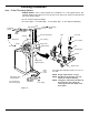
Softener Components Bypass Valve P/N 7129871 Power Supply Kit P/N 7238426 Motor Switch Kit P/N 7285910 Valve Kit P/N 7238557 Motor Plate P/N 7231385 Cam & Gear Kit P/N 7254252 Electronic Control Board P/N 7327534 Resin Tank Assembly Model MW-30: P/N 7269273 Model MW-40: P/N 7256220 Float Kit P/N 7238476 Locking Plate P/N 7225499 Valve Cover P/N 7085263 Installation Adaptor Kit P/N 7254260 Rotor/Seal Kit P/N 7238468 Nozzle & Venturi Kit P/N 7238450 Faceplate & Salt Hole Cover Kit P/N 7301473 Salt S
Warranty MIRACLE WATER RESIDENTIAL WARRANTY Miracle Water guarantees to the original owner, that: For a period of ten (10) years from date of purchased, the salt storage tank and fiberglass mineral tank will not rust, corrode, leak, burst, or in any other manner, fail to perform their proper functions; and that For a period of one (1) year after installation, all other parts will be free of defects in material and workmanship and will perform their normal functions.