
Specifications


6
C. Evacuation and Testing
After initial purging with nitrogen during and after brazing,
and with the Service Valves on the CU in the shipping
position (closed = clockwise, full in), evacuate the A-Coil
and Refrigerant Line Set to less than 200 microns for a
minimum of 20 minutes. Isolate the evacuation pump, and
fully open the service valves to release the refrigerant into
the A-Coil. Ensure all valve caps are restored securely and
properly tightened after this process is completed.
D. Horizontal Installation
Use hangers and rods to suspend the Air Handler Unit off of
a surface.
CAUTION – A full-sized secondary drain plan with its
own drain is required under the entire AHU when water
leakage is a concern, and all condensate drains must be
protected from freezing.
CAUTION – Additional splash guards may be necessary
to extend the condensate drain pan for returning potential
condensate blow-off back to the condensate pan.
E. Supplemental Electric Heat
The AHU is approved for use only with ECONAR electric
supplemental heat for use only on top discharge vertical
installations. Use a separate duct-installed heater for
horizontal applications. Field installation of ECONAR
electric supplemental heat in the field requires loosening
and lowering the electric control box during this installation
and then restoring the electrical control box to its original
location and mounting.
V. DUCT SYSTEM / BLOWER
Ductwork must have the capacity to handle the air volume
required for proper heating and cooling. Undersized duct
work will cause noisy operation and poor heat pump
operating efficiencies due to lack of airflow.
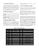
Metal ductwork should be used, and flexible connectors are
required for discharge and return air duct connections. See
Table 3 for acceptable duct sizes. A duct installed in an
uninsulated space should be insulated on the outside to
prevent heat loss, absorb noise, and prevent condensation
from collecting on the ductwork.
The Two Stage AHU is standard with a variable speed
Electronically Commutated Motor (ECM) blower motor.
The ECM motor converts 230 Volts AC to internal DC
power and then modulates the DC power to run the motor at
various speeds. There are different CFM outputs in each of
the four blower speed ranges (Low, Medium, Medium-
High, or High). Important – The blower will not operate
properly if ductwork is not attached to supply a static
pressure for the blower motor to work against. Important
– The blower compartment access door must be on for the
unit to run properly. Blower motors may overheat if run for
extended periods of time without a load. Note – refer to
the ECM Motor Troubleshooting Guide at the rear of this
manual if problems occur with the ECM motor.
Table 3 - Duct Sizing Chart
Acceptable Branch Duct Sizes
Acceptable Main or Trunk Duct Sizes
CFM
Round
Rectangular
Round
Rectangular
50
4”
4x4
75
5”
4x5, 4x6
100
6”
4x8, 4x6
150
7”
4x10, 5x8, 6x6
200
8”
5x10, 6x8, 4x14, 7x7
250
9”
6x10, 8x8, 4x16
300
10”
6x14, 8x10, 7x12
350
10”
6x20, 6x16, 9x10
400
12”
6x18, 10x10, 9x12
10”
4x20, 7x10, 6x12, 8x9
450
12”
6x20, 8x14, 9x12, 10x11
10”
5x20, 6x16, 9x10, 8x12
500
10”
10x10, 6x18, 8x12, 7x14
600
12”
6x20, 7x18, 8x16, 10x12
800
12”
8x18, 9x15, 10x14, 12x12
1000
14”
10x18, 12x14, 8x24
1200
16”
10x20, 12x18, 14x15
1400
16”
10x25, 12x20, 14x18, 15x16
1600
18”
10x30, 15x18, 14x20
1800
20”
10x35, 15x20, 16x19, 12x30, 14x25
2000
20”
10x40, 12x30, 15x25, 18x20
2200
22”
10x40, 15x25, 20x20
2400
22”
12x40, 16x25, 20x20
Tables calculated for 0.05 to 0.10 inches of water friction per 100’ of duct. At these duct design conditions, along with the pressure
drop through the filter, the total design external static pressure is 0.20 inches of water.