
Specifications


12
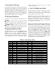
XIV. WIRING DIAGRAMS
Wiring Diagram, Vara 2 Plus Split Air Handler Models [FSx-1-2xV]
1-Phase
Power
Blu
FSx-x-2xV (Variable Speed Blower)
Air Handler Unit
Electrical Diagram
Rev _, 12/2010 80-0069
GRN
WHT
BLK
Equip Gnd
Power
Block
RED
1
2
3
4
5
DC
Blower
Motor
1 2 3 4 5 7 11 12 13 14 15
Blu
R
LOW
MED
HIGH
Adjust
A B C
D
A B C
D
A B C
D
+
-
Wht
Brn
BLK
Equip Gnd
Power Block
E2, 4.8kW
E1, 4.8kW
Blu
HL1, 150
HL2, 150
BLK
BLK
BLK
RED
RED
HL3, 135
Blu
ECONAR Slide-In Heater
(Optional FSx-x-xEx)
Grn/Blu
Grn/Rd
Wht/Blu
Red
Blk
Grn
Red
Red
Brown
White
Blu
Compressor Unit
BLK
208V
Yel
24V Transf
6
Y
2
E R G Y C
W
Yel
Grn/Blu
Org
Wht/Rd
1-Phase
Power
1 – Blue (X)
2 – White (W)
3 – Blue (X)
4 – Grn/Red (Md)
5 – Wht/Red (Lo)
6 – Yel (Y)
7 – Orange (+ / -)
11 – Wht/Blu (Hi)
12 – Red (R)
13 – Black (E)
14 – Grn/Blu (Y
2
)
15 – Green (G)
BLOWER MOTOR
CONTROL WIRES
Blu
Wht
Blk
Grn
E1, 2 Electric Elements
HL High Limit
Factory Low Voltage
Factory Line Voltage
Field Line Voltage
Field Low Voltage
BLOWER SPEEDS
A = Future Use
B = FS5
C = FS4
D = FS3
+ = Incr CFM 10%
- = Decr CFM 10%
Y
2
E R G Y
O
XW