
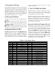
Specifications


8
down after the run time is complete. Ramping of the ECM
motor allows for quieter operation and increased comfort. It
may take a few seconds for the blower to start when the
thermostat initially calls for heating or cooling, and for the
blower to stop after the thermostat is satisfied.
2. Supplemental Electric Heat for 2
nd
Stage
24Vac applied to the W terminal on the wiring block of an
AHU equipped with Supplemental Electric Heat will
energize an electric heat contactor to power a 5kW heat
element of supplemental electric heat.
24Vac applied to the E terminal on the wiring block of an
AHU equipped with Supplemental Electric Heat will
energize both electric heat contactors to power 10kW of
supplemental electric heat.
If the application requires 10kW of supplemental electric
heat, jumper the W and E terminals on the AHU thermostat
wiring block.
VIII. STARTUP / CHECKOUT
Before applying power, check the following items:
- All construction dust has been cleaned up and all sheet-
rocking is completed. Construction dust, especially sheet-
rock dust, can plug the air coil and block airflow. Ensure
the air coil and air filter are clean before starting the unit.
- Low voltage wiring and any additional control wiring is
complete. Set the room thermostat to the “OFF” position.
- All high voltage wiring is correct including fuses,
breakers, and wire sizes.
You may now apply power to the unit.
- Place the thermostat in the “FAN ON” position. The
blower should start. Check airflow at the registers to make
sure that they are open and that air is being distributed
throughout the house. When airflow has been checked,
move the thermostat to the “FAN AUTO” position. The
blower should stop.
The following steps will ensure your system is operating
properly.
- Turn the room thermostat up to its highest temperature
setting. Place the thermostat to the "HEAT" position. The
blower will start.
- Next, turn the thermostat down to its lowest setting. Place
the room thermostat in the "COOL" position. The blower
will start.
- Set the room thermostat for normal operation.
- Instruct the owner on correct operation of the room
thermostat and fan coil. The unit is now operational.
IX. SERVICE
Properly installed, the ECONAR Air Handler Unit requires
only minor maintenance, such as periodic cleaning of the air
filter and the air coil. Consider setting up regular service
checkups with your Enertech dealer.
A. Air Filter
The air filter should normally be replaced once a month
during normal usage. During extreme usage, or if system
performance has decreased, the filter should be replaced
more often. A washable electrostatic air filter can be cleaned
by spraying water through the filter in the direction opposite
to the indicated airflow. This can be done in a garage with a
garden hose, or in a large sink. Soap may also be used to
provide extra cleaning. Light dirt may be vacuumed off.
A dirty filter will increase static pressure to the system and
cause the variable speed ECM blower motor to increase
speed to maintain airflow levels; and in extreme cases, the
blower will not be able produce the correct amount of
airflow. These system changes will cause higher airflow
noise, more power consumption, and reduced heating or
cooling capacity.
B. Preseason Inspection
Before each season, the air coil, drain pan, and condensate
drain should be inspected and cleaned as follows:
- Turn off circuit breakers.
- Remove access panels.
- Clean air coil by vacuuming with a soft-brush attachment.
- Remove any foreign matter from the drain pan.
- Flush pan and drain tube with clear water.
- Replace access panels and return power to the unit.
CAUTION – Servicing systems using R410A refrigerant
requires special consideration (Refer to ECONAR
Instruction 10-2016 for more detail.). Always install a new
filter/dryer after replacing a refrigeration component
(compressor, etc.) and evacuate down to 150 microns.
C. Thermostatic Expansion Valve
Important – The TEV has an internal check valve to
control refrigerant in one direction and bypass refrigerant in
the opposite direction. A replacement TEV must be installed
correctly with the TEV Inlet orientated to the external
refrigerant liquid line.
X. ROOM THERMOSTAT
OPERATION
Installations may include a wide variation of available
electronic room thermostats, and most of them require to be
configured by the Installer (according to the Installation
Guide included with the thermostat) and checked out after
being installed.
Important – At a minimum:
1. Ensure the thermostat is set up for the “System Type” it
is installed on.
2. Change other Installer Settings only if necessary.
3. Remember to press “Done” to save the settings and to
exit “Installer Setup.”