Inside the Two Stage Air Handler Engineering Specifications & Installation/Operating Instructions Two Stage Split System Air Handler Unit FS3-x-2xV thru FS5-x-2xV Series
Two Stage Air Handler Unit
TABLE OF CONTENTS Section Title Page I. Introduction to ECONAR Heat Pumps 2 II. Applications 3 III. Available Models Capacity Ratings, Configuration Options, Physical Data, Electrical Data, Blower Performance Data 3 IV. Unit Location / Installation A. Air Handler Unit B. Refrigeration Line Set Installation C. Evacuation and Testing D. Horizontal Installation E. Supplemental Electric Heat 5 V. Duct System / Blower 6 VI. Electrical Service 7 VII. 24 Volt Control Circuit A. Transformer B.
I. INTRODUCTION TO ECONAR HEAT PUMPS WARNING – Service of refrigerant-based equipment can Enertech Global, LLC, is home to ECONAR geothermal heat pumps, a brand that has been in Minnesota for more than twenty years. The cold winter climate has driven the design of ECONAR heating and cooling equipment to what is known as a "ColdClimate" geothermal heat pump. This cold climate technology focuses on maximizing the energy savings available in heating dominated regions without sacrificing comfort.
II. APPLICATIONS ECONAR Split System geothermal heat pumps consist of an Air Handler Unit (AHU) and a fully-charged Compressor Unit (CU) to offer an extremely efficient and safe way of providing the primary space heating and all the cooling for many applications (see Figure 1). III. AVAILABLE MODELS Capacity Ratings Air Flow Ratings Capacity (CFM, Typical) (Tons, Typical) 910 -FS3-x-2xV 1180 3 1295 -FS4-x-2xV 1680 4 1425 -FS5-x-2xV 1850 5 *Note: CFM should be as specified plus up to 10%.
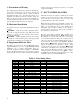
Physical Data Description FS3 or 4 FS5 4-ton 5-ton Expansion Device – Thermostatic 4.44 Ft2, 15fpi Air Coil Type – High Density A-Coil 4 Rows Quantity of Air Coil Rows ECM Fan Motor Type 3/4 Fan Motor (HP) 10x8 Fan Wheel (dia. x width) – ECM Motor 55 Transformer (VA) 230 Unit Weight (lbs)* Note: Unit weight includes pallet and packing materials. Electrical Data (all HCAR-type circuit breaker per NEC) Voltage Total Min. Max Model Frequency (Hz) Phase HP Blower FLA LRA FLA Amp.
IV. UNIT LOCATION / INSTALLATION Inspect for shipping damage immediately at delivery, and file claims immediately with the shipping company. Check to ensure that units have correct model numbers, electrical ratings, and accessories that match the original order. CAUTION – Units must be kept in an upright position during transportation or installation, or severe internal damage may occur.
and then restoring the electrical control box to its original location and mounting. C. Evacuation and Testing After initial purging with nitrogen during and after brazing, and with the Service Valves on the CU in the shipping position (closed = clockwise, full in), evacuate the A-Coil and Refrigerant Line Set to less than 200 microns for a minimum of 20 minutes. Isolate the evacuation pump, and fully open the service valves to release the refrigerant into the A-Coil.
VI. ELECTRICAL SERVICE Note – Always refer to the inside of the electrical box cover for the correct wiring diagram, and always refer to the nameplate on the exterior of the cabinet for the correct electrical specifications. WARNING – ELECTRICAL SHOCK CAN CAUSE PERSONAL INJURY OR DEATH. Disconnect all power supplies before installing or servicing electrical devices. Only trained and qualified personnel should install, repair or service this equipment.
down after the run time is complete. Ramping of the ECM motor allows for quieter operation and increased comfort. It may take a few seconds for the blower to start when the thermostat initially calls for heating or cooling, and for the blower to stop after the thermostat is satisfied. 2.
4. Run the system through all modes of operation in the thermostat instructions to ensure correct operation. If you have additional questions, please refer to the installation manual that was sent with the thermostat. XI. TROUBLESHOOTING GUIDE FOR UNIT OPERATION PROBLEM Entire unit does not run POSSIBLE CAUSE Blown Fuse or Tripped Circuit Breaker Broken or Loose Wires Voltage Supply Low CHECKS AND CORRECTIONS Replace fuse or reset circuit breaker. (Check for correct size fuse and circuit breaker.
XII. TROUBLESHOOTING GUIDE FOR ECM BLOWER PROBLEM Motor rocks slightly when starting Motor won’t start •No movement CHECKS AND CORRECTIONS •This is normal start-up for ECM. •Wait for completion of ramp-up at start. •Check power at motor. •Check low voltage (24 VAC R to X) at motor. •Check low voltage connections (G, Y, W2, R, X) at motor. •Check for unseated pins in connectors on motor harness. •Test with a temporary jumper between R and G. •Check motor for a tight shaft. •Perform Moisture Check*.
XIII.
XIV.
Greenville, IL & Mitchell, SD info@enertechgeo.com www.gogogeo.com 90-1093 Rev A (2011-008) | ©2012 Enertech Global, LLC.