MC Toolkit User Manual Doc. No.
Copyright, Notices and Trademarks Copyright 2010 by Honeywell International Inc. Revision 12, May 2013 While this information is presented in good faith and believed to be accurate, Honeywell disclaims the implied warranties of merchantability and fitness for a particular purpose and makes no express warranties except as may be stated in its written agreement with and for its customers. In no event is Honeywell liable to anyone for any indirect, special or consequential damages.
About This Document Abstract This document describes how to use MC Toolkit product, which consists of MC Toolkit application software and FDC application software.
Copyright, Notices and Trademarks Support and contact info United States and Canada Contact: Honeywell Process Solution Global Technical Support - Phone: 001-800-423-9883 Customer Service (HFS) - Phone: 001-800-343-0228 Outside United States - Phone: 001-215-641-3610 Calls are answered by dispatcher between 6:00 am and 4:00 pm Mountain Standard Time. Emergency calls outside normal working hours are received by an answering service and returned within one hour. Email support: ask-ssc@honeywell.
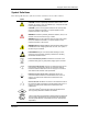
Copyright, Notices and Trademarks Symbol Definitions The following table lists those symbols used in this document to denote certain conditions. Symbol Definition CAUTION: Indicates a potentially hazardous situation which, if not avoided, may result in minor or moderate injury. It may also be used to alert against unsafe practices. CAUTION symbol on the equipment refers the user to the product manual for additional information. The symbol appears next to required information in the manual.
Copyright, Notices and Trademarks Acronyms and definitions Table 1 Acronyms and Definitions Term Description DD Device Description File DDL Device Description Language DE Digitally Enhanced Device The hardware that is responsible for sensing the conditions present in a process and communicating this information to the Pocket PC. These conditions may include pressure, temperature. Examples of devices include the ST, STT.
Contents Support and contact info.......................................................................................... iv 1. INTRODUCTION ............................................................................ 1 1.1 Overview of MC Toolkit .................................................................................. 1 Purpose/Scope .................................................................................................................... 1 Product Description .....................
Contents 3.7 DE/ HART Modem Firmware ......................................................................... 22 Checking the Modem Firmware version...........................................................................22 3.8 Connecting MC Toolkit to a device .............................................................. 24 Connecting to a device through PDA and modem (MCT101) .........................................24 Connecting to a device through MC Toolkit (MCT202) ..........................
Contents 5.3 MC Toolkit Application Software Display Conventions ............................ 69 Navigation .......................................................................................................................... 69 Menu Bar ............................................................................................................................ 69 File Menu ............................................................................................................................
Contents 8. APPENDIX A: APPLICATION NOTES ...................................... 141 8.1 Application Notes ........................................................................................ 141 Synchronization between PDA and PC ..........................................................................141 File Transfer......................................................................................................................145 9. APPENDIX B: ...........................................
Tables Table 1 Acronyms and Definitions .................................................................................. vi Table 3 Components of MCT202 assembly .................................................................. 17 Table 4 Generic UI elements ......................................................................................... 34 Table 5 FDC homepage elements ................................................................................. 35 Table 6 Device homepage elements .........
Figures Figure 1-1 Components of the MC Toolkit ....................................................................... 2 Figure 1-2 MCT202 (rugged and intrinsically safe models) ............................................. 3 Figure 2-1 Honeywell ST 3000/ ST 800 Smart Transmitter - Analog mode .................... 8 Figure 2-2 Honeywell Analog Value Scaling .................................................................. 10 Figure 2-3 Honeywell DE Mode Value Scaling ......................................
1. Introduction 1.1 Overview of MC Toolkit Purpose/Scope This manual is intended to facilitate the use of the Honeywell MC Toolkit communications tool. It is assumed that you are skilled in the use and maintenance of process transmitters in process control, or that you are under direct supervision of others with the appropriate skills.
1. Introduction 1.1. Overview of MC Toolkit Product Description The Honeywell Multi Communication (MC) Toolkit is a handheld communication package that enables convenient and reliable communications with smart field devices such as valves, actuators, transmitters etc. MC Toolkit is a smart solution for configuring, calibrating, monitoring, and diagnosing the devices supporting Honeywell Digitally Enhanced (DE) or HART communication protocols.
1. Introduction 1.1. Overview of MC Toolkit MCT202 The MCT202 has following options: • Ruggedized version: Environmentally hardened with no approvals. • Zone 2 approvals: Intrinsically-safe version available with FM Class I, Div 2, and ATEX Zone 2 approvals. • Zone 1 approvals: Intrinsically-safe version available with FM Class I, Div 1, and ATEX Zone 1 approvals.
1. Introduction 1.2. Transmitter Type and Communication Mode Software components The Honeywell MC Toolkit consists of two software applications: • The MC Toolkit application software is used for configuring, calibrating, monitoring, and diagnosing the Honeywell Digital Enhanced (DE) devices. • Field Device Configurator (FDC) application software is used for configuring, calibrating, monitoring, and diagnosing HART devices.
1. Introduction 1.3. Type of Procedure 1.3 Type of Procedure The MC Toolkit is designed to provide these basic functions: • Configuration • Calibration • Monitoring • Diagnostics Depending on combinations of factors such as transmitter type, and communications mode, some procedures such as monitoring the performance of a transmitter can be straightforward and innocuous, but in some cases can also require special preparation and precautions. 1.
1. Introduction 1.4. Prerequisites DE/HART Modem Firmware Version MC Toolkit Release 4.0 requires DE / HART modem firmware version 2.0 or above. To check the firmware version and to upgrade it to the version required, refer to section 3.5 Start up, Shutting down the MC Toolkit and 3.6 Application icons.” and section 3.7“DE / HART Modem Firmware Upgrade”.
2. Before you begin 2.1 Calibration requirements Input calibration Input calibration of pressure transmitters should be done only when necessary, and should be done only under conditions that will ensure accuracy: • The transmitter should be taken out of service, and should be moved to an area with favorable environmental conditions: clean, dry, and temperature-controlled. • The source for the input pressure must be very precise, and certified for correct operation.
2. Before you begin 2.2. Transmitter/Communication characteristics Figure 2-1 Honeywell ST 3000/ ST 800 Smart Transmitter - Analog mode The characterization constants, which are written at the factory, are derived from highly precise testing of the sensor's response over a range of temperatures, and from the Lower Range Limit (LRL) to the Upper Range Limit (URL) of the sensor.
2. Before you begin 2.2. Transmitter/Communication characteristics Digital to-Analog Conversion and Transfer The digital-to-analog converter (D/A) shown at key number (5) in Figure 2-1is shown as a box with a dotted line to indicate that analog output mode is a user-selectable feature, for use in an application whose receiving equipment requires an analog input.
2. Before you begin 2.2. Transmitter/Communication characteristics Honeywell transmitter analog value scaling URV Figure 2-2 Honeywell Analog Value Scaling Digital (Communications Signal) Input/Output As indicated at the right of Figure 2-2, communications between the MC Toolkit and the Honeywell Smart Transmitter consist of digital pulse strings, with rapid transitions of current level between (approximately) 4 mA and 20 mA.
2. Before you begin 2.2. Transmitter/Communication characteristics Honeywell transmitter output-Digital enhanced mode Most of the operation of the Honeywell Smart Pressure Transmitter Digital Enhanced (DE) mode is similar to that of operation in the analog mode.
2. Before you begin 2.2. Transmitter/Communication characteristics In multi-drop mode, up to 16 transmitters in HART 5 (addresses 0-15) and up to 64 transmitters in HART6/7 (addresses 0-63) can exist on the two-conductor network, which precludes analog transmission methods. In this case, the same FSK modulation method is used for conveying levels of PV (and other variables) and also for communications.
2. Before you begin 2.2.
2. Before you begin 2.2.
3. Getting Started 3.1 MC Toolkit Installation MC Toolkit software is fully loaded in the factory on all new orders. The following provisions are available for all the existing MC Toolkit users. Existing MCT202 Users: Migration path is available for Existing MCT202 users having modem firmware version 1.0 as well as 2.0. • Users having MCT202 with Modem firmware version 2.
3. Getting Started 3.2. MC Toolkit Assembly 3.2 MC Toolkit Assembly MCT101 assembly Figure 3-1 shows the MCT101 assembly. Figure 3-1 MCT101 assembly Table 2 describes the components of the MCT101 assembly. Table 2 Components of MCT101 assembly Item Description Device connector cable for connecting the modem and the field device. Probes at the end of the device connector cable for connecting to the field device. Device connector port of the modem. Battery box.
3. Getting Started 3.2. MC Toolkit Assembly MCT202 assembly Shows the MCT202 assembly. Figure 3-2 MCT202 assembly Table 3 describes the components of the MCT202 assembly. Table 3 Components of MCT202 assembly Item Description Positive and negative test leads. Connecting terminals for test leads. Test leads to connect to the field device. Functional keys which can be configured. Navigational keys. Button for powering on/powering off the MC Toolkit. 5 pin charging plug with USB connector. Reset buttons.
3. Getting Started 3.3. Safety instructions 3.3 Safety instructions General safety instructions Persons using the unit must observe the standard safety regulations and read the certificate to prevent incorrect operation or misuse of the unit. For MCT101 The general safety instructions while using MCT101 are as follows: • Ensure that all the screws are tightened before using the modem. • Ensure that the communication port connector’s screws are tightened.
3. Getting Started 3.3. Safety instructions - Do not transmit near persons with pacemakers! - Permission to use electronic devices in airplanes is up to the respective airline. - Avoid effects of elevated heat: Do not place the device near heat sources, such as radiators, airconditioner air exit openings, stoves or other devices (including amplifiers) that radiate heat. - Avoid effects of moisture. - Do not put any objects into the product: Do not put objects into the housing or other product openings.
3. Getting Started 3.4. Battery and Power Supply 3.4 Battery and Power Supply MCT101 uses a 3V Lithium battery (model # - CR-V3). To replace or insert the battery, refer to the MCT101 MCT101 modem battery replacement section 7.1. For battery care of MCT202, refer to MCT202 battery replacement section 7.2. For the Power supply information for MCT202, refer to “ i.
3. Getting Started 3.5. Start up, Shutting down the MC Toolkit 3.5 Start up, Shutting down the MC Toolkit The section explains how to start the MC Toolkit. Starting the MCT101 Press the Power button on the PDA and wait until the main PDA window appears displaying the Start icon. Shutting down the MCT101 Press the Power button on the PDA and hold it for few seconds to shutdown.
3. Getting Started 3.7. DE/ HART Modem Firmware 3.7 DE/ HART Modem Firmware Checking the Modem Firmware version Tap on the MCToolkitCodeDownload icon.
3. Getting Started 3.7. DE/ HART Modem Firmware Select Modem Diagnostics under the Modem Menu. Modem Diagnostic screen will be displayed Figure 3-5 Modem Menu Figure 3-6 Modem Diagnostics screen Check and verify that the Modem Firmware version field displays 2.0. If it is less than 2.0, upgrade the modem firmware using the Instructions guide 34-ST-25-33 that is shipped with the MC Toolkit product.
3. Getting Started 3.8. Connecting MC Toolkit to a device 3.8 Connecting MC Toolkit to a device Connecting to a device through PDA and modem (MCT101) Figure 3-7 shows how a field device is connected through MCT101. Refer to the MCT101 assembly for more details.
3. Getting Started 3.8. Connecting MC Toolkit to a device Connecting to a device through MC Toolkit (MCT202) Figure 3-8 shows how a field device is connected through MCT202. Refer to the MCT202 assembly for more details.
3. Getting Started 3.8.
3. Getting Started 3.9. Connecting MC Toolkit to a PC 3.9 Connecting MC Toolkit to a PC Connecting MCT101 1. Insert the PDA into the docking station. 2. Connect the USB cable to a free USB port on the PC. 3. Follow the Active Sync/Mobile Device Center instructions appearing on the screen to establish the connection between the PDA and the PC. Connecting MCT202 1. Connect the USB connection cable to a free USB port on the PC. 2.
3. Getting Started 3.10. Types of input methods 3.10 Types of input methods The MC Toolkit application allows you to provide inputs through various mechanisms supported through Windows Mobile platform, they are, Keyboard, Block Recognizer, Letter Recognizer, and Transcriber. On the other hand the FDC application supports the input through a custom keypad which supports numeric or alphanumeric keys depending upon the input context.
3. Getting Started 3.10. Types of input methods Character input using Block Recognizer For character input using block recognizer, perform the following steps. 1. Tap on the arrow 2. Use the stylus to provide a character input to the letter pad at the bottom of the screen. The character strokes are then converted to typed text on the screen as shown below in Figure 3-12. at the bottom right corner of the display and tap on Block Recognizer.
3. Getting Started 3.10. Types of input methods Character input using Letter Recognizer For character input using letter recognizer, perform the following steps. 1. Tap on the arrow 2. Use the stylus to provide character inputs between the lines which appear at the bottom of the screen. The character input is recognized and displayed on the screen as shown in Figure 3-13. at the bottom right corner of the display and tap on Letter Recognizer.
3. Getting Started 3.10. Types of input methods Character input using Transcriber For character input using transcriber, perform the following steps. 1. Tap on the arrow 2. Use the stylus to input the characters by writing them on the screen, in cursive, print or, mixed handwriting. The character input is recognized and displayed on the screen as shown in Figure 3-14. at the bottom right corner of the display and tap on Transcriber.
3. Getting Started 3.10. Types of input methods Input dialog in FDC Depending upon the context of the data, FDC smartly presents an alphanumeric or numeric keypad for data entry as shown in Figure 3-15.
4. Managing HART Devices using FDC Application Software 4.1 Starting FDC To start FDC, perform the following steps. 1. Turn on the MC Toolkit. Note: For information on turning on the MC Toolkit, refer to section 3.5 Start up, Shutting down the MC Toolkit and 3.6 Application icons. 2. Select FDC from the Start menu. The FDC homepage appears.
Managing HART Devices using FDC Application Software 4.2. Overview of FDC homepage Table 4 describes the UI elements that appear on all FDC pages. Table 4 Generic UI elements Items Description Title bar – Displays the current page title. Page icon – Displays current page icon Icon 1 Icon 2 Exit button – Tap to quit the current page. Workspace – Consists of various menu items for working with FDC. Menu bar – Consists of options for navigation and selection. 4.
4. Managing HART Devices using FDC Application Software 4.2. Overview of FDC homepage Table 5 lists the items that appear on the FDC homepage and its descriptions. Table 5 FDC homepage elements Items Description Screen title. Tap to quit FDC. Tap to view the application information. Tap to navigate to Online Configuration screen. Tap to navigate to Offline configuration screen. Tap to navigate to Manage DDs screen. Tap to navigate to Settings screen. Tap to select the highlighted menu option.
Managing HART Devices using FDC Application Software 4.2. Overview of FDC homepage DD selection Use the following options to configure FDC to select DD files when a DD with matching device revision is not available. − Use DD file of previous device revision: Use this option to automatically load a device with a DD file having device revision lower than that of the device. − Use generic DD file: Use this option to automatically load the device with an appropriate generic DD file.
4. Managing HART Devices using FDC Application Software 4.3. Customizing the settings 4.3 Customizing the settings Modifying device identification settings Using the Device Identification settings, you can choose how to detect a device. Devices can be detected using poll address or device tag name. By default, devices are detected using poll address zero. However, you can modify these settings based on how you want to detect devices. To modify the device detection settings, perform the following steps.
Managing HART Devices using FDC Application Software 4.3. Customizing the settings 4. If you want to load devices with a generic DD files even if a DD matching the device revision is available, select the checkbox under the Always Use Generic option. Modifying other default settings Using the “Others” tab under settings, you can set the following: • • Threshold percentage for notifying a low storage space warning. By default, the notification for percentage of available storage card space is set as 5%.
4. Managing HART Devices using FDC Application Software 4.4. Managing DD files 4.4 Managing DD files Overview Using Manage DDs, you can view, add, or delete DD files for devices. A list of already available DD files is maintained in the DD Library. FDC lists the installed DD files in a hierarchy as below: Manufacturer Device Type DevRev xx, DDRev yy DevRev pp, DDRev qq Add a DD file To add a DD file for a device, perform the following steps. 1. From the FDC homepage, tap Manage DDs > Select.
Managing HART Devices using FDC Application Software 4.4. Managing DD files Delete a DD file Using this option, you can delete a particular version of a DD file. To delete a DD file for a device, perform the following steps. 1. From the FDC homepage, tap Manage DDs > Select. The Manage DDs dialog box appears. 2. You can choose to delete DD(s) in one of the following ways: a) b) c) 3.
4. Managing HART Devices using FDC Application Software 4.5. Overview of device configuration Validating a manually edited library Besides using the Add/Delete DD features, advanced users may also manipulate a DD library by directly editing the contents of the FDC\Library folder. DD files can also be transferred directly to this location by accessing the SD Card on MCT101 through a card reader and/or by connecting the MCT101 or MCT202 to a PC.
Managing HART Devices using FDC Application Software 4.6. Online configuration 4.6 Online configuration Online Configuration option provides you a set of functions with which you can perform various operations on a device with active communication link. These operations primarily include configuration, calibration, monitoring, and diagnostics of a HART device. Typically, these operations could be realized through various constructs exposed by the DD file of the device.
4. Managing HART Devices using FDC Application Software 4.6. Online configuration Table 6 lists the entry points and its descriptions. Table 6 Device homepage elements Items Description Tap Information tab to view the device identity related information. Tap Functions tab to choose from various options to configure, calibrate, monitor and diagnose the device Tap My Views tab to create and use your own custom views. Tap Tools tab to use FDC specific tools applicable to the device.
Managing HART Devices using FDC Application Software 4.6. Online configuration Tabs on the Device Home page The following are the options that are available on the device homepage • Information tab: Use this option to view the device identity related information. You can view the manufacturer name, device type, device revision, DD revision, and universal revision of the HART device.
4. Managing HART Devices using FDC Application Software 4.6. Online configuration For the sake of explanation, the pages that appear on navigating through the device specific entry points are called as “Device Configuration” pages in this document. However it must be noted that this does not prohibit you from performing other device operations as explained above. Online Entry Point: When you tap on to open the online tab, the device configuration screen appears as shown in the following figure.
Managing HART Devices using FDC Application Software 4.6. Online configuration A Device Configuration page is split horizontally into an upper and lower pane. The top pane displays the set of hierarchically organized groups called menus and the bottom pane displays the set of corresponding items under each menu. The bottom pane has three columns: Label, Value, and Unit. FDC also displays an icon against each item to visually identify different types of items.
4. Managing HART Devices using FDC Application Software 4.6. Online configuration Viewing different type of variables The variables when present under a menu are typically displayed with their label, value and unit. Note that for some variables, the unit may not be applicable. Some variables just display a hexadecimal value against their labels. When you select such a variable, “View” option gets enabled on the menu bar. Tap View to see the details of the selected variable.
Managing HART Devices using FDC Application Software 4.6. Online configuration Updating the device with edited variables Editing the variables does not automatically send them to the device. You must explicitly perform the action of sending the values to the device to update it. Once you have edited one or more variables as explained above, the icon at the bottom left corner of the page becomes enabled. To update the device with edited variables, perform the following steps. 1.
4. Managing HART Devices using FDC Application Software 4.6. Online configuration If the variables are updated successfully to the device, status appears as SUCCESS in green color; and if failed, status appears as FAILED in red color. 5. Tap Note: Use Revision 12 May 2013 to close the current page and to return to the previous page. to reset the selected variable’s values. Double tap on FAILED status to view the reason.
Managing HART Devices using FDC Application Software 4.6. Online configuration Searching for an item Often it is very tedious and time consuming to navigate to a specific item through a deeply nested menu structure. FDC allows you to search for an item in a particular entry point. Using Search option, you can search for a device variable which is specific to the entry point, perform the following steps. 1. Under the Functions tab, choose Online. 2. Tap icon on the bottom left part of the page.
4. Managing HART Devices using FDC Application Software 4.6. Online configuration Device Health Indicator and Details Using the standard features of the HART communication protocol FDC provides an indicator of the device’s health through a LED indicator on the title bar of each page. Quite often the details of such health indicators are available through different variables under different menus. FDC however provides an entry point on the functions tab to view the details of the device health indicators.
Managing HART Devices using FDC Application Software 4.6. Online configuration The graph screen appears. 6. Tap Options > Select Waveform. The Select Waveform dialog box appears. 7. Select the required waveform and tap OK to view the graph of the selected waveform. 8. Tap Options > View Legends. The View Legends dialog box appears with the legends. 9. Tap Close to close the View Legends dialog box. 10. Tap Options > Edit Waveform. The Edit Waveform dialog box appears.
4. Managing HART Devices using FDC Application Software 4.6. Online configuration Charts A chart is a graphical representation of the device data as it changes over time. The x-axis in a chart is always time. A chart may display one or more trends which are collectively called as a Source. Further, a chart may have more than one source which you may select to view. The colors, labels, and axes of charts may vary from device to device as defined in the DD file.
Managing HART Devices using FDC Application Software 4.6. Online configuration • Sweep: A Sweep chart updates from left to right overwriting the oldest displayed historical data in the process. A vertical line separates the old data from the new and scrolls as the new data displays. When the plot reaches the right most end of the chart, the data begins plotting again from the left end of the chart. Scope: A Scope chart updates from left to right.
4. Managing HART Devices using FDC Application Software 4.6. Online configuration Gauge: A gauge chart formats the device data into a view similar to circular, dial-type analog meter. The indicator is a pointer that rotates as the current value varies with time. • Revision 12 May 2013 Bar Charts: A bar chart displays the device data in bars varying with time.
Managing HART Devices using FDC Application Software 4.6. Online configuration To view a chart, perform the following steps. 1. On the Device Home page, tap Functions tab. 2. Tap Online > Select. 3. The Device Configuration page appears which displays the top and bottom panes. 4. Navigate to the desired menu. The bottom pane will display items under that menu. Select any chart from the list of available charts which appear on the bottom pane. 5. Tap View. The chart page appears. 6.
4. Managing HART Devices using FDC Application Software 4.6. Online configuration Grids A grid is a structure to display related device information in tabular form. The data may be organized with either the column headers or with the row headers. To view a grid, perform the following steps. 1. On the Device Home page, tap Functions tab. 2. Tap Online > Select. 3. The Device Configuration page appears which displays the top and bottom panes. 4. Navigate to the desired menu.
Managing HART Devices using FDC Application Software 4.6. Online configuration Images An image is a picture of an object related to the device as defined by the DD file. An image may display anything from company information/logo to device image and drawings, and so on. To view an image, perform the following steps. 1. On the Device Home page, tap Functions tab. 2. Tap Online > Select. 3. The Device Configuration page appears which displays the top and bottom panes. 4. Navigate to the desired menu.
4. Managing HART Devices using FDC Application Software 4.6. Online configuration Executing methods on a device To execute methods on devices, perform the following steps. Note: For example, consider the following scenario to execute Loop test. 1. On the Device Home page, tap Functions tab. 2. Tap Online > Select. 3. The Device Configuration page appears which displays the top and bottom panes. 4. Navigate to the desired menu. The bottom pane will display items under that menu. 5.
Managing HART Devices using FDC Application Software 4.6. Online configuration Saving device history FDC provides you a feature wherein you can save the device configuration snapshot as history. This history record may then be transferred to a central asset management database such as FDM. Using this feature you can save the device configuration snapshot as device history of a connected device at any given time in a predefined location. The following are the features of save device history option.
4. Managing HART Devices using FDC Application Software 4.6. Online configuration 7. If a history record for this device already exists, the following warning message appears. 8. Tap Yes to overwrite the existing name. A overwrite success message appears. 9. Tap OK to return to Device Home page. Exporting device history records to FDM The history snapshot saved in FDC can be imported into FDM for record and audit purposes. This is enabled by the standard Import/Export wizard in FDM.
Managing HART Devices using FDC Application Software 4.6. Online configuration Exporting device history records to Documint To export device history from FDC and import it in FDM, perform the following steps. 1. Connect your MC Toolkit handheld to your computer as described earlier. 2. Browse to the folder on your computer, SD Card > FDC > Resources > History. 3.
4. Managing HART Devices using FDC Application Software 4.6. Online configuration Note: To view the custom views, tap My View 1 > Select. The My View 1 page appears. The editing and other features are as explained in the earlier sections.
Managing HART Devices using FDC Application Software 4.7. Offline configuration 4.7 Offline configuration Overview Offline Configuration refers to configuring a device when the device is not physically present or communicating with the application. This process enables you to create and save a configuration for a device, even when the device is not there physically. Later when the device becomes available with live communication, the same configuration can be downloaded to the device.
4. Managing HART Devices using FDC Application Software 4.7. Offline configuration Deleting offline configuration Using this feature you can delete an offline configuration template. To delete an offline configuration, perform the following steps. 1. On the FDC homepage, tap Offline Configuration > Select. The Offline Configurations page appears. 2. Select the required offline configuration template from the list. 3. Tap Options > Delete. A warning message appears. 4.
Managing HART Devices using FDC Application Software 4.7. Offline configuration 6. Tap Next. The Offline – Review and Send page appears with the list of selected variables. 7. Tap Send and the process to send the variables to the device starts. Once the downloading is complete, the following page appears. Note: If the variables are downloaded successfully, status appears as SUCCESS in green color; and if failed, status appears as FAILED in red color. 8. 66 Tap Finish to return to FDC Homepage.
5. Managing DE Devices using MC Toolkit Software 5.1 Starting MC Toolkit application To start the MC Toolkit application, perform the following steps. 1. Turn on the MC Toolkit. Note: For information on turning on the MC Toolkit, refer to section 3.5 Start up, Shutting down the MC Toolkit and 3.6 Application icons. 2. Select the MCToolkit icon The MC Toolkit homepage appears. 5.2 Overview of MC Toolkit Homepage MC Toolkit Homepage allows user to select the Configuration Mode; Online or Offline.
Managing DE Devices using MC Toolkit Software 5.2. Overview of MC Toolkit Homepage Offline: “Offline” button allows you to select a basic offline template, edit the parameters and download to a device after establishing connection. The updates to the parameters can also be saved into the file without actually downloading to the device. Complete detail is provided under “Offline Configuration” section 5.
5. Managing DE Devices using MC Toolkit Software 5.3. MC Toolkit Application Software Display Conventions 5.3 MC Toolkit Application Software Display Conventions Navigation Menu Buttons In general, selecting a button in a display will call up the next-lower-level display, whose title is the same or similar to the label on the button. A menu tree for Honeywell DE Displays is given under Menu Bar, Menu Selections and HELP display table.
Managing DE Devices using MC Toolkit Software 5.3.
5. Managing DE Devices using MC Toolkit Software 5.3. MC Toolkit Application Software Display Conventions File Menu File (Startup screen) Exit Closes the MC Toolkit application Options Calls up the MC Toolkit OPTIONS Dialog. See MC Toolkit Options dialog for details. General Options allows selection of COM Port. For the PDA it is always COM1. Offline Configuration Options has Offline Configuration Settings.
Managing DE Devices using MC Toolkit Software 5.3. MC Toolkit Application Software Display Conventions Modem Menu Note: Before you begin Upload or Download operation it is important to make sure that the modem status is good. Select Modem\Modem Diagnostics and make sure that BOTH Modem Battery and Modem Status are OK. Do not continue in case of any bad status. Modem Diagnostics Modem Battery: Must display Ok to proceed Modem Version: Current Modem firmware version on the xx.
5. Managing DE Devices using MC Toolkit Software 5.3. MC Toolkit Application Software Display Conventions Help Menu HELP display The Help display is available whenever the MC Toolkit is active. It includes three groups of topics, each of Selectable from the Help Menu - General - DE Each group includes a list of topics. Each topic (in blue, underlined letters) is selectable to provide direct access to the Help information.
Managing DE Devices using MC Toolkit Software 5.4. Overview of device configuration Data Entry and Display Key number / Description Illustration: Key Numbers 1. Box with no arrow and with gray background indicates a readonly (R/) field. Numeric or text values in transmitter are displayed only; user entry or modification is not permitted. 2. Box with white background and with no arrow indicates Read/Write (R/W) text or numeric input field.
5. Managing DE Devices using MC Toolkit Software 5.5. Online configuration 5.5 Online configuration Detecting and loading a device “Online” button allows you to establish connection to a device and do Online operations Online Mode Introduction This section contains procedures for using the MC Toolkit application software to communicate with Honeywell DE Transmitters. On the Homepage select “Online” button to proceed with Online Configuration features.
Managing DE Devices using MC Toolkit Software 5.5.
5. Managing DE Devices using MC Toolkit Software 5.5. Online configuration Summary of Operating Procedures To access displays for Honeywell DE Transmitters: • Start the MC Toolkit application; the MC TOOLKIT ... display will appear. Refer to 5.1 Starting MC Toolkit application. • Upload the database from the transmitter. (The QUICK MONITOR display will enable viewing of key parameters before taking the time for database uploading.) The DE MAIN MENU appears. (Refer to 5.
Managing DE Devices using MC Toolkit Software 5.5.
5. Managing DE Devices using MC Toolkit Software 5.5. Online configuration Procedural Considerations De device Upload, Configuration and Calibration procedures are listed in the tables below. Table 12 DE Upload Procedures DE Upload Procedures Select the Online button This Warning message appears. If the MC Toolkit is connected to a DE Device, select the OK button. Select the Upload button; the wait cursor and progress bar appear.
Managing DE Devices using MC Toolkit Software 5.5.
5. Managing DE Devices using MC Toolkit Software 5.5. Online configuration Table 13 DE Main Menu Procedures DE Main Menu Procedures DE Main Menu (ST 3000) (STT 3000) Note: This message appears if the
Managing DE Devices using MC Toolkit Software 5.5. Online configuration General (ST 3000 / ST 800) DE Main Menu Procedures (STT 3000) PV Type (r/w) Select: Dual Range (STDC) or Single Range or Single Range w/SV Communication Mode (r/w) Select: Analog or DE 4 Byte or DE 6 Byte FS Direction (r) (Upscale or Downscale; selection is jumpered in the transmitter). Line Filter (r) Select: 50hz or 60hz. T/C Fault Detect (r/w): Select: Enabled or Disabled.
5. Managing DE Devices using MC Toolkit Software 5.5. Online configuration DE Main Menu Procedures Calibration For more information, refer to: Table 14, Table 15, Table 16, Table 17. Meter Hardware (r) Type designation of meter associated with the transmitter Meter Units (r/w) Selection EUs for Local Meter Custom Units (r/w) (Refer to Transmitter User Manual).
Managing DE Devices using MC Toolkit Software 5.5. Online configuration DE Main Menu Procedures Critical Status Latching Select the Read button to display Select Enabled or Disabled. the lowest and the highest PV Auxiliary Configure values since last read. NAMUR Select Enabled or Disabled. (Disable requires that Write Protect is set to Not Write Protected.) CJ Temp. Enter External Cold Junction Temperature. Select the Read HI/LO button to call up the READ HIGH/LOW PV display.
5. Managing DE Devices using MC Toolkit Software 5.5. Online configuration DE Main Menu Procedures The configuration will be saved in the *.xml file under SD Card/CFG_MCT folder on your MC Toolkit / MCT 202. You can copy the saved configuration file to PC and view it in a browser as it is, or Import the data into Excel for further file management. Follow “How to view the Saved Configuration file and Import to Excel”? Section 5.6.
Managing DE Devices using MC Toolkit Software 5.5. Online configuration Table 14 Input Calibration (DE Transmitters) – Correct Input (Zero), LRV, URV; Reset Corrects Input Calibration (DE Transmitters) - Correct Input (Zero), LRV, URV; Reset Corrects Requirements: Objective(s): • Input source, with accuracy of at least 0.04% • resistor, at least 250-ohms • Voltmeter or Ammeter • 24 Vdc Power Supply (nominal) • Clean work area with suitable environmental conditions.
5. Managing DE Devices using MC Toolkit Software 5.5. Online configuration Input Calibration (DE Transmitters) - Correct Input (Zero), LRV, URV; Reset Corrects Set-Up On Bench A typical bench set-up is shown at right. Connect the MC Toolkit as indicated, and establish communication with the transmitter. For these procedures, components in the current loop are not critical, provided that they support reliable communication between the transmitter and the MC Toolkit.
Managing DE Devices using MC Toolkit Software 5.5. Online configuration Input Calibration (DE Transmitters) - Correct Input (Zero), LRV, URV; Reset Corrects Call up Calibration display Navigate to the DE Calibration display as follows. Select Back (go to DE Main Menu), then select the Calibration button. Correct Input at Zero Select Corr. Input (zero). This message appears. As indicated below, this procedure will shift the slope up or down to eliminate the error at the zero reference.
5. Managing DE Devices using MC Toolkit Software 5.5. Online configuration Input Calibration (DE Transmitters) - Correct Input (Zero), LRV, URV; Reset Corrects Correct Input at LRV Select the Correct LRV button. This message appears. Select the OK button; this message appears. (ST 3000 / ST 800) Adjust the PV input pressure to the exact value of the LRV entered in the DE CONFIGURE display. Correct Input at LRV Select the Correct LRV button. This message appears.
Managing DE Devices using MC Toolkit Software 5.5. Online configuration Input Calibration (DE Transmitters) - Correct Input (Zero), LRV, URV; Reset Corrects Reset Corrects If corrects should not be overwritten with factory values, select the No button. Note: This function commands the transmitter to overwrite all user input corrections with factory default ("characterization") values. If corrects need to be overwritten, select the Yes button.
5. Managing DE Devices using MC Toolkit Software 5.5. Online configuration Table 15 Output Calibration - Loop Test Output Calibration - Loop Test Objective Verify the integrity of electrical components in the output current loop. Connect the MC Toolkit as indicated, and establish communication with the transmitter. For these procedures, values of components in the current loop are not critical, provided that they support reliable communication between the transmitter and the MC Toolkit.
Managing DE Devices using MC Toolkit Software 5.5. Online configuration Output Calibration - Loop Test Example The displays at right illustrate a Set Output selection and setting of Other, at 57 %. Caution: !! Unintended exit in Output Mode? !! 92 If Yes was selected as above in the CONFIRM! popup message, it is possible to exit MC Toolkit application while the Output is fixed at constant current.
5. Managing DE Devices using MC Toolkit Software 5.5. Online configuration Table 16 DE Output Calibration - Trim DAC Current DE Output Calibration - Trim DAC Current Overview of Objectives For a DE transmitter operating in analog mode in a user's application, calibrate the analog output current to the PV input range. That is, adjust the output such that 4 mA corresponds to 0% (LRV), and 20 mA corresponds to 100% (URV). Call up display In the DE MAIN MENU, select the Calibration button.
Managing DE Devices using MC Toolkit Software 5.5. Online configuration DE Output Calibration - Trim DAC Current Trim Output Current Select the Set Output To 0% button or the 100% button. The message popup at right appears. Caution: In Output Mode, output current is fixed at 0% or 100%. Ensure that the loop is in Manual control. Select the Yes button, and at the meter, observe the level of loop current. NOTE: On the voltmeter, 4 mA corresponds to 1 volt.
5. Managing DE Devices using MC Toolkit Software 5.5. Online configuration Table 17 DE Calibration - Apply Values DE Calibration - Apply PV values to Set LRV and Set URV Overview • Manually set the Process Variable input to 0%, and apply this value to Set LRV; of • Manually set the Process Variable input to 100%, and apply this value to Set URV. Objectives: NOTE: This procedure applies to DE Transmitters operating in DE Mode as well as to those operating in Analog (current) Mode.
Managing DE Devices using MC Toolkit Software 5.5. Online configuration DE Calibration - Apply PV values to Set LRV and Set URV Set LRV While observing the PV value at the physical process element, (using a sight glass, for example) adjust the Process Variable to the desired Minimum (0 %) level, then select Set LRV If the displayed value is satisfactory, select Yes to copy the Input Value to the LRV in the transmitter. If not, select NO and repeat this step.
5. Managing DE Devices using MC Toolkit Software 5.6. How to view the Saved Configuration file and Import to Excel 5.6 How to view the Saved Configuration file and Import to Excel Revision 12 May 2013 1. Setup Activesync connection between your PC and MC Toolkit 2. Right click on ActiveSync icon on the System trey and select Explore 3. Select My Windows Mobile-Based Device\SD Card\CFG_MCT\*.XML file that you would like to copy to the PC. 4.
Managing DE Devices using MC Toolkit Software 5.6. How to view the Saved Configuration file and Import to Excel 5. Go to a location on the PC; for example c:\MCT 6. Right click and select Paste. Now you can double click on the .xml file to open in the Internet Explorer Browser.
5. Managing DE Devices using MC Toolkit Software 5.6.
Managing DE Devices using MC Toolkit Software 5.6. How to view the Saved Configuration file and Import to Excel How to Import the data from the xml file to Excel? 1. Open Microsoft Excel 2. Select Data / Get External Data / From Other Sources / From XML Data Import, and Browse to the .xml file you saved on your PC. This will Import data in the below format.
5. Managing DE Devices using MC Toolkit Software 5.6. How to view the Saved Configuration file and Import to Excel This can be saved as an Excel file for further file management.
Managing DE Devices using MC Toolkit Software 5.7. Offline Configuration 5.7 Offline Configuration Using Offline configuration, you can select a basic offline template, edit the parameters and download to a device after establishing connection. The updates to the parameters can also be saved into the file without actually downloading to the device. Offline Mode Introduction On the MC Toolkit Home page select “Offline” to proceed with Offline Configuration features.
5. Managing DE Devices using MC Toolkit Software 5.7. Offline Configuration FILE MANAGEMENT screen On the “FILE MANAGEMENT” screen, accept the last file that was accessed or you can select “Browse” to open up the “Open” dialog and browse for a different file that has the offline configurations. MC Toolkit will be shipped with 2 files MCToolkit.xml and TEMPLMCT.xml. The MCToolkit.xml file consists of default configurations for all the supported DE devices.
Managing DE Devices using MC Toolkit Software 5.7. Offline Configuration Edit parameter Set, 1, 2, 3: Selection of these buttons open up the Parameters Screens Save to File: Allows you to save the changes made to the offline configuration. Download to Device: Allows downloading the selected configuration to the device after establishing connection MC Toolkit Options dialog Select the File / Options menu or ‘Options’ button on the Select Device Type dialog to open up the MC TOOLKIT OPTIONS screen.
5. Managing DE Devices using MC Toolkit Software 5.7. Offline Configuration Parameters screens To access the parameters screens select one of the 3 buttons under the “Edit Parameter Set” caption on the Select Device type dialog.
Managing DE Devices using MC Toolkit Software 5.7.
5. Managing DE Devices using MC Toolkit Software 5.7. Offline Configuration Parameter set 3 Figure 5-8 STT25M and 25D models Figure 5-10 DE STT350 Figure 5-9 ST3000 DE The following options are available on the parameters screens: Revision 12 May 2013 • Select the “Save” button to save the changes to the database. • Select the “Undo” button to undo the last change. Depending upon the parameter, a group of related parameters will be undone on selecting the “Undo” button.
Managing DE Devices using MC Toolkit Software 5.7. Offline Configuration Save to File in Offline Mode Selecting Yes adds the current configuration into the current working file. Selecting No, brings up the “Save As” screen. The location and folder are set to SD Card and CFG_MCT. You can type in a new name for the file. The default name will be “New1”.
5. Managing DE Devices using MC Toolkit Software 5.7. Offline Configuration Template File MC Toolkit will be shipped with a template file named TEMPLMCT.XML” with some default configurations. The user cannot modify it. If the user selects this file for loading and editing parameters, he gets the message shown in Figure 5-12 Honewyell DE Save Template Screen.
Managing DE Devices using MC Toolkit Software 5.7. Offline Configuration Download in Offline mode Apply power to the device. Connect the PPC to the modem with the serial cable and connect the modem to the device. Select “DOWNLOAD to Device” to establish connection to the device and Download the selected configuration to the connected device. Download confirmation screen will be displayed as in Figure 5-14 Download in Offline Mode.
5. Managing DE Devices using MC Toolkit Software 5.7. Offline Configuration Download Parameter List The table below lists all the Parameters available+ in the MC Toolkit offline configuration file Parameters Index (Index of the parameters in the configuration file) Example Values Properties (R – Read only; R/W – Read / Write) 0 Bus Type DE R 1 Device STT 3000 R 2 Tag ID STT250Ta R/W 3 Serial Number B044929237 R 4 Manufacturer Honeywell R 5 Model Number 2.
Managing DE Devices using MC Toolkit Software 5.7.
5. Managing DE Devices using MC Toolkit Software 5.7.
Managing DE Devices using MC Toolkit Software 5.7. Offline Configuration Field Damping (ST only) (seconds) Value 0.00 1.00 8.00 0.16 2.00 16.0 0.32 4.00 32.0 T/C J T/C N RTD-Cu10 T/C K RTD-PT100J RTD-Cu25 T/C T Millivolts T/C–RH Radiamatic T/C S RTD-PT100D T/C–W5W26 T/C R RTD-PT200 T/C–W3W25 T/C E RTD-PT500 Ohms T/C B RTD-Ni500 T/C-NiNiMo Sensor Type (ST only) DP AP GP Line Filter (STT only) 50 Hz 0.48 Sensor Type (STT only) 60 Hz Scratch pad 32 chars.
5. Managing DE Devices using MC Toolkit Software 1.1. 5.8 Reference Data Glossary Item Definition Description Conformity Response form of sensor. User selection of PV conversion algorithm: Linear or Square Root D/A Trim Digital to Analog Trim Adjustment to digital-to analog (output) conversion algorithm that aligns minimum and maximum values of scaled digital range to minimum (0%) and maximum (100%) values of analog output.
Managing DE Devices using MC Toolkit Software 5.8. Reference Data Item Definition Description SV Secondary Variable A measured physical value of a physical property (e.g., temperature) that relates to the measured primary physical property (e.g., pressure). SV Units Secondary Variable Units Standard scale of values of an SV, chosen by you for convenient display and interpretation.
5. Managing DE Devices using MC Toolkit Software 5.8. Reference Data Honeywell DE Fields and Values Dialog Device Info General DE Configure Field Value Tag ID Tag id (8 chars.) Type Transmitter type Firmware version Firmware version of the transmitter Serial number Serial number of transmitter Scratch pad 32 chars.
Managing DE Devices using MC Toolkit Software 5.8. Reference Data Dialog DE Configure (continued) Field Value Damping (ST only) (seconds) 0.00 1.00 8.00 0.16 2.00 16.0 0.32 4.00 32.0 0.
5. Managing DE Devices using MC Toolkit Software 5.9. XML Database (Samples) Dialog Local Display (ST 800) Field Value Display Hardware Display Installed, Display Not detected Display Units % mBar mHg @ 0C inH2O @ 39°F bar mH2O 4°C mmHg @ 0°C g/cm² GPM psi kg/cm² GPH KPa mmH2O @ 4°C Custom MPa 5.
Managing DE Devices using MC Toolkit Software 5.9. XML Database (Samples) 400.0 0.00 0 0 Scratch Test 09-20-2007 12:25:25 0.00000 400.
6. Troubleshooting 6.
Troubleshooting 6.2. FDC application software troubleshooting scenarios 6.2 FDC application software troubleshooting scenarios Application Startup Problem Unable to launch or open FDC application. Cause The cause may be any one of the following: • .NET CF 3.5 is not installed. • FDC is installed in device memory instead of SD card. • One or more dependent files are corrupt. You can resolve by performing the following: Resolution • Installing .NET CF 3.5. • Re-installing FDC in SD card.
6. Troubleshooting 6.2. FDC application software troubleshooting scenarios Problem Detection at poll address 63 in case of detection by poll address using range (0-63) failed sometimes Cause Potential issue with the modem Resolution You can resolve by performing the following: • Retry • Reduce the poll address ranges and try detecting the device Write parameter Problem Sometimes it is observed that Send status in download screen may display failure but actually written to the device.
Troubleshooting 6.2. FDC application software troubleshooting scenarios Problem Sometimes the curves in the graphs may not appear as expected. Cause FDC has limits on the number of data points it supports for waveforms on Graphs Resolution known limitation Save History Problem Save history operation may fail in specific scenarios.
6. Troubleshooting 1.1. Resolution You can resolve by performing the following: • Retry offline download for failed items. Problem Manufacturer and Device Type name may not be displayed for a certain scenarios.
Troubleshooting 6.3. MC Toolkit application software troubleshooting scenarios 6.3 MC Toolkit application software troubleshooting scenarios Login scenario Problem Unable to launch or open MC Toolkit application. Cause The cause may be any one of the following: • MC Toolkit is installed in device memory instead of SD card. • One or more dependent files are corrupt. Resolution You can resolve by performing the following: • Re-installing MC Toolkit in SD card.
6. Troubleshooting 6.3. MC Toolkit application software troubleshooting scenarios MC TOOLKIT ERROR MESSAGES MESSAGE Description Resolution / CORRECTIVE ACTION Checksum error on Modem Response! Erroneous data packet received at the modem A noisy environment can cause this error. Repeat the command again. Com Port Read Timeout! Error associated with the Communication port Ensure that the Honeywell supplied modem cable is used and that the connections are secure.
Troubleshooting 6.3. MC Toolkit application software troubleshooting scenarios MESSAGE Invalid Handle Value! Description Error associated with the Communication port Resolution / CORRECTIVE ACTION Make sure ActiveSync/Mobile Device Center is not running. If Several programs are active, try closing one or more open programs. Stop the MC Toolkit application by doing File | Exit and restart the program. Use the Pocket PC hardware reset. See your Pocket PC documentation reset the unit.
6. Troubleshooting 6.3.
Troubleshooting 6.3. MC Toolkit application software troubleshooting scenarios Description Resolution / CORRECTIVE ACTION Transmitter-Modem Receive Buffer overflow! Data bytes from the transmitter to the modem is more than expected This could be the result of having older version of the modem. Upgrade the modem firmware using ModemCodeDownload program Unknown Error! Unexpected error MCT101 Users: This could indicate a defective modem. Repeat the command again.
6. Troubleshooting 6.3. MC Toolkit application software troubleshooting scenarios DE Device error messages Description Resolution / CORRECTIVE ACTION Write NVM Failed Write to transmitter Non-Volatile Memory failed. Try the operation again, the transmitter was busy doing something else Unknown Device MC Toolkit does not support this transmitter. Check the list of supported devices Invalid Range User-entered value is too high or too low.
Troubleshooting 6.3. MC Toolkit application software troubleshooting scenarios MESSAGE Description The transmitter is in Output Mode. Are you sure you want to terminate the connection? User tried to Exit MC Toolkit application while the DE Transmitter is still in Output Mode. Same as Description The changes you have made are about to be sent to the transmitter. Continue? Values entered into this display will be written into transmitter memory.
6. Troubleshooting 6.3. MC Toolkit application software troubleshooting scenarios Offline configuration Error Messages MESSAGES DESCRIPTION Resolution / Corrective Action All the options are saved! Any changes made on the current dialog are saved Informational message Invalid file Selected file name is not found in the Pocket PC Informational message You have selected the Template file and you cannot modify it.
Troubleshooting 6.3. MC Toolkit application software troubleshooting scenarios Download failed! Could not download the selected configuration to the Device due to any of the following reasons: Try downloading to the right device Device mismatch Version incompatibility Communication errors Version incompatibility found! Some of the parameters in version X of the device are not supported in version Y of the device.
6. Troubleshooting 6.3. MC Toolkit application software troubleshooting scenarios Could not set one or all of the following parameters: Conformity, Damping! Do you want to proceed with the rest of the download? When the Write Conformity and Damping command fails, you get this message. You can abort the rest of the download or continue Same as the description Could not set the Scratch Pad! When the Write Scratch Pad command fails, you get this message.
Troubleshooting 6.3. MC Toolkit application software troubleshooting scenarios The current config. file ….XML has reached its limit of 200 Tag IDs / Records, please save the configuration to a new file The requirement was to support at least 100 Tag IDs. But the program allows to Save MAX 200 configurations / Tag IDs in the same file.
7. MC Toolkit Maintenance 7.1 MCT101 modem battery replacement When to replace battery The battery should be replaced: when one of these messages appears in the Modem Status box of the Modem Diagnostics screen. Low Battery -Unknown (after checking wiring connections) -ROM Failure -RAM Failure -in periodic maintenance, when voltmeter test indicates low voltage.
MC Toolkit Maintenance 7.1. MCT101 modem battery replacement How to replace battery Before replacing, obtain a new CR-V3p battery. Honeywell recommends Panasonic CR-V3p. Other models may perform adequately but not as well. WARNING ! Never remove the cover of the battery compartment, or attempt battery replacement in areas designated as having a potentially Explosive atmosphere. Step 138 Action 1 Remove the screw that holds the battery cover in place, and remove the cover from the battery compartment.
7. MC Toolkit Maintenance 7.2. MCT202 battery replacement 7.2 MCT202 battery replacement Battery Replacement The battery is not replaceable in the field. For Canada and North America Honeywell Field Solutions Customer Support contact the number listed in the front of this document. WARNING !! Due to certification requirements, all hardware maintenance issues of the MCT202 necessitate that the unit must be returned to Honeywell for factory servicing.
MC Toolkit Maintenance 7.3.
8. Appendix A: Application Notes 8.1 Application Notes Synchronization between PDA and PC Windws XP: ActiveSync/Mobile Device Center connection Connect the ActiveSync/Mobile Device Center cable from the PDA base to a USB port on the PC. ActiveSync/Mobile Device Center should start automatically. If your PDA is synched with the PC, you see the Screen Y. If the screen does not come up maximized, you will see the icon on your Desktop Taskbar. Double tap on the icon to maximize.
Appendix A: Application Notes 8.1. Application Notes If you do not see the Screen Y, select Start\All Programs\Microsoft ActiveSync/Mobile Device Center. It is likely that your PDA is not synched up with your PC and you will see the screen below. Select File/Connection Settings and set the Connection settings as below. Select OK. The Synch process should start now. If you are still not connected, then Soft Reset the PDA with the Sync cable still connected between the PDA base and the PC.
8. Appendix A: Application Notes 8.1. Application Notes Windows Vista and Windows 7: Mobile Device Center connection Connect the ActiveSync/Mobile Device Center cable from the PDA base to a USB port on the PC. Windows Mobile Device Center should start automatically. If your PDA is synched with the PC, you see the screen below. If the screen does not come up maximized, you will see the icon on your Desktop Taskbar. Tap on the icon to maximize.
Appendix A: Application Notes 8.1. Application Notes Select Mobile Device Settings and set the Connection settings as below. Select OK. The Synch process should start now. If you are still not connected, then Soft Reset the PDA with the Sync cable still connected between the PDA base and the PC.
8. Appendix A: Application Notes 8.1. Application Notes File Transfer File Transfer between Pocket PC and PC is achieved by the ActiveSync/Mobile Device Center interface. PC Activesync / Mobile Device Center PDA Upload Device Save to Do/wnload File Save History Send / Download to Device Figure 8-3 ActiveSync/Mobile Device Center file transfer ActiveSync/Mobile Device Center Establishes connection between PC and PDA. Allows you to copy files between PC and PPC once the connection is established.
9.1. MCT Power Save Guidelines 9. Appendix B: 9.1 MCT Power Save Guidelines When not in use, always turn off the PDA. Do not leave the MC Toolkit or FDC applications running if not in use; exit the applications to save modem battery.
10. Appendix C: Replacement Parts 10.1 MCT101 Replacement parts Table 18 MCT101 Replacement Parts Description Part Number Interface Hardware DE/HART Modem 51453372-501 Field Connection Cable (Modem-to-Transmitter) 6 Ft. - Standard 30752453-501 20 Ft.
10.
Revision 12 May 2013 MC Toolkit User Manual 149
Sales and Service For application assistance, current specifications, pricing, or name of the nearest Authorized Distributor, contact one of the offices below. ASIA PACIFIC EMEA NORTH AMERICA SOUTH AMERICA (TAC) Honeywell Process Solutions, Honeywell do Brasil & Cia hfs-tacsupport@honeywell.