
Installation Instructions


26
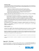
1.4 Step 4: Adjusting the Bed Beacon to Proper Field Range
1. Connect the AC Line Power Sensor to the Bed Beacon via any RJ11 jacks as shown in Figure 3.
2. Plug the patient bed’s AC power cord into a 120vAC power source. This will activate the Bed Beacon so
that the range setting and all testing can be performed. Refer to section 6 - Adjusting the Patient Zone -- in
the main section of this document for instructions on adjusting the communication range.
2. Cable Management
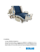
2.1 Step 5: AC Line Power Sensor Cable Routing
1. Place cable tie holders, cable ties and route AC Line Power Sensor cable to the Bed Beacon as shown
(see Figure 4 & 5). Make sure the mounting surfaces are clean and free of dirt and oil. A soft cloth
dampened with isopropyl alcohol works well to clean mounting surfaces.
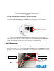
Figure 2.
The
AC Line Power Sensor
Installation Location on
the Bed
Figure 3.
Connecting the
AC Line Power Sensor
to the Bed Beacon via the RJ11 connector
AC Line Power
Sensor Cable RJ11
connectors
AC Line Power
Sensor attached to
power cord
Head of the bed Foot of the bed
Bed
Beacon
Cable
Ties