
User Manual


User and installer's manual
6
EN
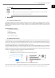
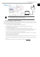
Figure 2.2. EASYNET web interface main screen. ECOFOREST heat pump (example).
Main screen fields
1. CENTRAL INFORMATION BAR.
This displays certain basic information about the device.
2. OPERATION PROGRAM.
This displays the device’s current operating program.
3. OPERATION MODE.
This displays the active operation modes of the device.
4. ALARM CODE.
This displays the current alarm status of the device.
▪ N: EASYNET GATEWAY connected to the ECOFOREST device.
▪ G040: Connection failure between EASYNET GATEWAY and the ECOFOREST device.
5. STATUS.
This displays the current status of the device and lets you change it.
6. USER MENU.
This lets you see and adjust the comfort parameters of the device.
7. INSTALLER MENU.
This lets you see the operating parameters of the device.
8. CONNECTION MODE.
This lets you see and configure the EASYNET GATEWAY's connection mode (see section 4).
NOTE
▪ The content of the EASYNET web interface menus may vary depending on the ECOFOREST equipment
that is connected to the EASYNET GATEWAY. Refer to the ECOFOREST device manual for more
information.
Once you access the different menus using the icons at the bottom of the main screen, you can navigate through the available
information in an intuitive way. The information will be displayed following the structure of the menu of the monitored ECOFOREST
device, so you can consult the device's own manual to find the information you need.
5
4
6
8
7
3
1
2