Installation Guide No. 135, 7/99 L00061 Eclipse AirHeat Burners AH Series version 2.
COPYRIGHT DISCLAIMER NOTICE LIABILITY AND WARRANTY 2 Copyright 1999 by Eclipse Combustion, Inc. All rights reserved worldwide. This publication is protected by federal regulation and shall not be copied, distributed, transmitted, transcribed or translated into any human or computer language, in any form or by any means, to any third parties, without the express written consent of Eclipse Combustion, Inc., Rockford, Illinois, U.S.A.
About this manual AUDIENCE This manual has been written for people who are already familiar with all aspects of a nozzle-mix burner and its add-on components, also referred to as “the burner system.” These aspects are: • installation • use • maintenance. The audience is expected to have had experience with this kind of equipment. PURPOSE The purpose of this manual is to ensure the installation of a safe, effective, and trouble-free combustion system is carried out.
DOCUMENT CONVENTIONS There are several special symbols in this document. You must know their meaning and importance. The explanation of these symbols follows below. Please read it thoroughly. d Danger: Indicates hazards or unsafe practices which WILL result in severe personal injury or even death. Only qualified and well trained personnel are allowed to carry out these instructions or procedures. Act with great care and follow the instructions.
Table of contents About this manual . . . . . . . . . . . . . . . . . . . . . . . . . . Audience . . . . . . . . . . . . . . . . . . . . . . . . . . . . . . . . . . . . Purpose . . . . . . . . . . . . . . . . . . . . . . . . . . . . . . . . . . . . . AirHeat Documents . . . . . . . . . . . . . . . . . . . . . . . . . . . Related Documents . . . . . . . . . . . . . . . . . . . . . . . . . . . . Document Conventions . . . . . . . . . . . . . . . . . . . . . . . . How to Get Help . . . . . . . . . . . . . . .
5 Maintenance & Troubleshooting . . . . . . . . . . . . . . Maintenance . . . . . . . . . . . . . . . . . . . . . . . . . . . . . . . . . . Monthly Checklist . . . . . . . . . . . . . . . . . . . . . . . . . . . . . Yearly Checklist . . . . . . . . . . . . . . . . . . . . . . . . . . . . . . . Troubleshooting Procedures . . . . . . . . . . . . . . . . . . . . 19 19 19 20 21 Appendix . . . . . . . . . . . . . . . . . . . . . . . . . . . . . . . . . . . 24 Conversion Factors . . . . . . . . . . . . . . . .
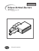
Introduction PRODUCT DESCRIPTION 1 Eclipse AirHeat v2.00 Burners are line type burners ideal for generating large volumes of clean, hot air. Applications include ovens, dryers, fume incinerators, and similar industrial equipment. Burners are constructed of aluminum burner bodies and diverging stainless steel air wings. The burner bodies supply fuel to the center of the air wings. The air and fuel mixture inside the burner is controlled to optimize emissions and efficiency. AirHeat v2.
Safety INTRODUCTION SAFETY 2 This section is provided as a guide for the safe operation of the AirHeat burner system. All involved personnel should read this section carefully before operating this system. d Danger: The AirHeat burners, described herein, are designed to mix fuel with air and burn the resulting mixture. All fuel burning devices are capable of producing fires and explosions if improperly applied, installed, adjusted, controlled, or maintained.
CAPABILITIES Only qualified personnel, with good mechanical aptitude and experience on combustion equipment, should adjust, maintain, or troubleshoot any mechanical or electrical part of this system. OPERATOR TRAINING The best safety precaution is an alert and trained operator. Train new operators thoroughly and have them demonstrate an adequate understanding of the equipment and its operation. A regular retraining schedule should be administered to ensure operators maintain a high degree of proficiency.
Installation 3 INTRODUCTION In this section you will find important notices about safe operation of the burner: HANDLING STORAGE Handling: 1. Make sure that the components are clean and free of damage. AND 2. Protect the components from weather, damage, dirt and moisture. • Transport in original shipping container • Do not drop 3. Protect the components from excessive temperatures and humidity. 4. Use appropriate support equipment, i.e. harnesses, straps, chains etc. when lifting burner components.
Electrical wiring All electrical wiring must comply with one of these standards: • • • • Gas Piping ANSI-C11981 EN 746-2 the electrical wiring must be acceptable to the local authority having jurisdiction All gas piping must comply with one of these standards: • • • • Where to get standards NFPA Standard 70 NFPA Standard 70 ANSI Z223 EN 746-2 the gas piping must be acceptable to the local authority having jurisdiction The NFPA Standards are available from: National Fire Protection Agency Batteryma
PRE-INSTALLATION CHECKLIST Air Supply If there are corrosive fumes or materials in the surrounding air, find an uncontaminated source to supply air to the burner. Observe ambient temperature limits as stated in Data 135. • Combustion Air From Outside Duct Provide an opening in the burner room of at least one square inch per 4000 BTU/hr (6 cm2 per 1 kW) to supply the burner intake with fresh, outdoor, combustion air.
BURNER MOUNTING (CONTINUED) In Duct Mounting When laying out the duct, allow enough length downstream of the burner to avoid flame impingement; see page 2 of Data 135 for flame lenghts. Provide at least 3” (76 mm) clearance between the burner and the top, bottom and sides of the duct. Profile plates are not required for good burner operation, but uniform velocity must be maintained for the full length of the burner. If velocity is not uniform, profile plates can be used to correct this condition.
BURNER MOUNTING (CONTINUED) Supply Piping • Locate the valve train close to the burner. The gas must reach the burner during the fixed trial for ignition. • Sufficiently size shut off valves in the valve train. • Make sure piping is large enough. • Minimize piping elbows. Pipe Connections • Installation of a pipe union in the gas line is recommended to simplify burner removal. • Use of flexible pipe is optional. Note: Flexible pipe causes higher pressure drops than standard pipe.
CHECK LIST AFTER INSTALLATION To verify the system was properly installed, perform the following checks: 1. Be sure there are no leaks in the gas lines. 2. Be sure all the components contained in the flame monitoring and control system are properly installed. This includes verifying that: • all the switches are installed in the correct locations. • all wiring and pressure lines are properly connected. 3. Be sure all components of the spark ignition system are installed and functioning properly. 4.
Adjustment, Start & Stop INTRODUCTION 4 In this chapter you will find instructions on how to start and stop a burner. The chapter begins with general instructions that are useful for adjustment. Danger: d The AirHeat burners, described herein, are designed to mix fuel with air and burn the resulting mixture. All fuel burning devices are capable of producing fires and explosions if improperly applied, installed, adjusted, controlled, or maintained.
There are two separate ignition procedures which depend upon whether or not a pilot is installed on the burner. Each procedure is unique and both are outlined below. Warning: Both procedures assume that a flame monitoring control system is installed and is serviceable. 1. Drive the gas control valve to low fire. w Step 3a: Ignite the burner (Option 1: Direct Spark Ignition)) n Note: All AirHeat burners are limited to direct spark ignition at inputs below 60% of maximum. 2.
Step 4: Set high fire gas 1. If the burner is ignited, set the main gas pressure regulator for 10” w.c. outlet pressure. 2. Drive the main gas control valve to high fire (full open). 3. Verify air flow with the burner firing, if necessary, repeat Step 2 “Set air flow”. 4. Make sure that pressure taps B and C are open. 5. Connect the manometer to taps B and C. 6. Measure the gas differential pressure. 7.
Maintenance & Troubleshooting INTRODUCTION 5 This chapter is divided into two sections: • Maintenance procedures • Troubleshooting guide Preventive maintenance is the key to a reliable, safe and efficient system. The core of any preventive maintenance system is a list of periodic tasks. MAINTENANCE Note: These are guidelines only. The customer should make the final determination on maintenance intervals and tasks to be performed while considering the working environment. Monthly Checklist 1.
Yearly Checklist 20 1. Leak test the safety shut-off valves for tightness of closure. 2. Test the pressure switch settings by checking the switch movements against pressure settings and comparing these with the actual impulse pressure. 3. Visually check igniter cable and connectors. 4. Be sure the following components are not damaged or distorted: • the burner bodies and air wings. • the igniter. • the flame sensors. Eclipse AirHeat v2.00, Installation Guide No.
TROUBLESHOOTING PROCEDURES PROBLEM Cannot initiate a start sequence. POSSIBLE CAUSE • Air pressure switch has not made contact. Check air pressure switch adjustment. Check air filter. Check blower rotation. Check outlet pressure from blower. • High gas pressure switch has activated. Low gas pressure switch has activated. Check incomming gas pressure; adjust if necessary. Check pressure switch setting and operation. • Purge cycle not completed. Check flame safeguard system or purge timer.
PROBLEM Start-up sequence runs but burner does not light. (continued) POSSIBLE CAUSE No ignition (continued): • The igniter needs cleaning. The igniter is not correctly grounded to the burner. Clean the threads on the igniter and the burner. NOTE: Do not apply grease to the threads on the igniter. • Igniter insulator is broken. Igniter is grounding out. Inspect the igniter. Replace if broken. • Gas valve does not open.
PROBLEM Main flame is uneven along the length of the burner. Main flame is yellow and long at high fire. CO emission is too high. POSSIBLE CAUSE SOLUTION • Air pressure drop/velocity is too low. Increase air pressure drop. • Poor air distribution in duct. Check profiling and duct obstructions. • Air wings are dirty, holes are clogged. Inspect and clean air wings if necessary. • Gas pressure too high at burner inlet. Check gas pressure against design. Adjust main gas pressure regulator.
Appendix CONVERSION FACTORS Metric to English. From To Multiply By cubic meter (m3) cubic foot (ft3) 35.31 cubic meter/hour (m3/h) cubic foot/hour (cfh) 35.31 degrees Celsius (ºC) degrees Fahrenheit (ºF) (ºC x 1.8) + 32 kilogram (kg) pound (lb) 2.205 kilowatt (kW) BTU/hr 3414 meter (m) foot (ft) 3.28 millibar (mbar) inches water column (“w.c.) 0.401 millibar (mbar) pounds/sq in (psi) 14.5 x 10⁻³ millimeter (mm) inch (in) 3.94 x 10⁻² MJ/m3 (normal) BTU/ft3 (standard) 2.
KEY TO SYSTEM SCHEMATICS Symbol Appearance These are the symbols used in the schematics. Name Remarks Bulletin/ Info Guide AirHeat NC Main Gas Shutoff Valve Train Eclipse Combustion, Inc. strongly endorses NFPA as a minimum Gas Cock Gas cocks are used to manually shut off the gas supply on both sides of the main gas shut-off valve train. 710 Solenoid valves are used to automatically shut off the gas supply on a bypass gas system or on small capacity burners.
Eclipse Combustion