
Installation guide


9
Eclipse RatioMatic Burners, RM Series, V5, Installation Guide 110, 11/11/2011
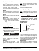
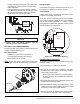
Figure 3.6. Refractory Block
Large Refractory Blocks
On sizes RM0300 through RM3000; the block must be
tightly surrounded by a collar made of brick, plastic
refractory, or a castable refractory of at least 4" (10 cm)
minimum thickness on all sides of the block. If the collar is
cast around the block, a thin plastic film (i.e. Saran Wrap
®
or Glad Wrap
®
) should be wrapped around the block to
keep moisture from leaching into it. The collar should be
anchored to the furnace shell with suitable anchors and
must be constructed to rest on a surface capable of
supporting its weight, such as a hearth or a solid refractory
or brick wall. For furnaces that are unable to support the
weight of the refractory block, a stainless steel shelf can be
welded to the shell to support the collar.
NOTE: All refractory blocks are cured at a minimum
temperature of 550°F (300°C) prior to shipment.
NOTE: The correct insulation of burner combustion blocks
in furnaces results in longer block life and adds value by
reducing downtime and maintenance.
Block Holder Temperature
Excessive block holder temperatures can cause
problems. Overheating can be reduced by carefully
sealing the burner blocks in the wall to prevent the
leakage of hot gases back to the furnace shell.
In high temperature (>1,400°F, 760°C) fiber-wall furnace
installations, the length of the metallic wrapper should
extend no farther than the point in the wall where the
interface temperature is higher than 1800°F (760°C).
Vertical Down Firing Blocks (Figure 3.6)
1. Down firing blocks may be suspended by customer
supplied hangers attached to the burner body mounting
bolts.
2. Hangers should be attached to structural support.
Gas Piping
Burner Piping
The burner is factory assembled and shipped as ordered.
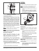
NOTE: If it is necessary to redirect piping, be sure the:
• ratio regulator spring column is pointing up.
• arrow on the ratio regulator points in the direction of
gas flow.
• integral fuel orifice and o-rings are re-installed in
the same orientation with respect to the fuel flow.
• same straight run of pipe remains between the
ratio regulator and the burner.
Figure 3.7. Burner Piping
Supply Piping
Inlet pressure to the ratio regulator must stay within
specified limits. Refer to the appropriate RatioMatic
datasheet.
• Locate the valve train close to the burner. The gas
must reach the burner during the fixed trial for
ignition.
• Appropriately size shut off valves in the valve train.
• Make sure piping is large enough to accommodate
flow required to meet burner input.
• Minimize piping elbows.
• If a reducing nipple is necessary, install it at the inlet
to the burner proportionator. Do not use a reducing
bushing in the proportionator inlet.
Bypass Start Gas Piping (Optional for RM0050-
RM0700 Only)
Install the piping as shown in the schematics using the
following guidelines:
• Locate the bypass start gas solenoids close to the
burner. The gas must reach the burner during the
trial for ignition period.
• Minimize piping elbows.
NOZZLE
POSITION
2
9
10
3
8
7
1
4