
Installation guide


10
Eclipse RatioMatic Burners, RM Series, V5, Installation Guide 110, 11/11/2011
• Install an adjustable limiting orifice (ALO) for start
gas adjustment. Refer to Bulletin 728 and 730 for
further information.
• Include a straight run of pipe at least 8" (192mm)
long before (upstream from) the start gas orifice
(optional) and at least 4" (96mm) long after
(downstream from) the start gas orifice.
Figure 3.8. Bypass Start Gas Piping
■ Please verify that piping complies with all
applicable codes and/or standards.
Pilot Valve Trains (RM1000-RM3000)
The pilot gas valve train should be connected as close as
possible to the pilot adjusting cock.
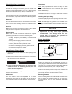
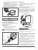
Pipe Connections
• Installation of a pipe union in the gas line is
recommended to simplify burner removal.
• Use of flexible pipe is optional.
NOTE: Flexible pipe causes higher pressure drops than
standard pipe. Consider this when sizing your gas lines.
Figure 3.9. Piping Connections
Piping Support
Use brackets or hangers to support the gas piping. If you
have questions, consult your local gas company.
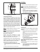
Control Motor
Install a control motor to modulate the air butterfly valve if
not previously installed on the burner.
NOTE: Be sure the control motor shaft and air butterfly
valve shaft are aligned properly. In some cases washers
may be used as shims (stacked 0, 1, or 2 high) to ensure
proper alignment. Additionally, a flexible coupling can be
used to handle minor misalignment.
Figure 3.10. Control Motor Mounting
Checklist After Installation
To verify the system was properly installed, perform the
following checks:
1. Be sure there are no leaks in the gas lines.
2. Be sure all the components contained in the flame
monitoring and control system are properly installed.
This includes verifying that:
• all the switches are installed in the correct locations.
• all wiring, pressure, and impulse lines are properly
connected.
3. Be sure all components of the spark ignition system are
installed and functioning properly.
4. Be sure the blower rotates in the proper direction. If the
rotation is incorrect, have a qualified electrician rewire
the blower to rotate in the proper direction.
5. Be sure all valves are installed in the proper location
and correctly oriented relative to the flow direction.
NC
NC
Main gas
shut-off
valve train
NOTICE
Bracket
Pipe Union
Set
Screws
Motor
Shaft
Control
Motor
Coupling
BV
Shaft