Installation Guide 110 11/11/2011 Eclipse RatioMatic Burners RM Series Version 5
Copyright consequential, including but not limited to loss of use, income, or damage to material arising in connection with the sale, installation, use of, inability to use or the repair or replacement of Eclipse’s products. Copyright 2010 by Eclipse, Inc. All rights reserved worldwide.
Table of Contents Introduction .............................................................................................. 4 Product Description....................................................................... 4 Audience ....................................................................................... 4 RatioMatic Documents .................................................................. 4 Purpose.........................................................................................
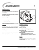
1 Introduction Product Description The RatioMatic is a nozzle-mix type burner designed for direct and indirect air heating and oven applications up to 1900°F(1040°C). The burner package includes a combustion air blower and an air/gas ratio regulator to fire over a wide gas turndown range with controlled ratio.
2 Safety Introduction This section is provided as a guide for the safe operation of the RatioMatic burner system. All involved personnel should read this section carefully before operating this system. Safety DANGER ■ The RatioMatic burners, described herein, are designed to mix fuel with air and burn the resulting mixture. All fuel burning devices are capable of producing fires and explosions if improperly applied, installed, adjusted, controlled, or maintained. ■ Do not bypass any safety feature.
3 Installation In this section you will find information and instructions needed to install the burner and system components. Handling & Storage Handling Where to Get the Standards: • Make sure that the area is clean. • Protect all components from weather, damage, dirt and moisture. • Protect the components from excessive temperatures and humidity. • Take care not to drop or damage components. Storage • Make sure the components are clean and free of damage.
Checklist Before Installation Air Supply Provide an opening in the burner room of at least one square inch per 4000 BTU/hr (6 cm2 per 1 kW) to supply the burner intake with fresh, outdoor, combustion air. If there are corrosive fumes or materials in the surrounding air, find an uncontaminated source to supply air to the burner, or provide a sufficient air filtering system.
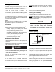
“C” “C” CAUTION ■ Placing insulation around the combustor beyond the burner nozzle position will decrease combustor life. RM0050 - RM0700 RM1000 - RM3000 3. No gasket is supplied or required between the burner and combustor. Figure 3.2. Mounting Pattern Chamber Wall Silicon Carbide (SiC) Combustor Only Make sure the chamber wall is strong enough to support the weight of the burner . If necessary, reinforce the mounting area.
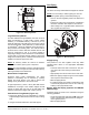
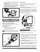
7 3 Gas Piping Burner Piping 1 The burner is factory assembled and shipped as ordered. 4 NOZZLE POSITION NOTE: If it is necessary to redirect piping, be sure the: • ratio regulator spring column is pointing up. • arrow on the ratio regulator points in the direction of gas flow. • integral fuel orifice and o-rings are re-installed in the same orientation with respect to the fuel flow. • same straight run of pipe remains between the ratio regulator and the burner. 8 2 9 10 Figure 3.6.
• Install an adjustable limiting orifice (ALO) for start gas adjustment. Refer to Bulletin 728 and 730 for further information. • Include a straight run of pipe at least 8" (192mm) long before (upstream from) the start gas orifice (optional) and at least 4" (96mm) long after (downstream from) the start gas orifice. NC Use brackets or hangers to support the gas piping. If you have questions, consult your local gas company.
Adjustment, Start & Stop DANGER ■ The RatioMatic burners, described herein, are designed to mix fuel with air and burn the resulting mixture. All fuel burning devices are capable of producing fires and explosions if improperly applied, installed, adjusted, controlled, or maintained. ■ Do not bypass any safety features. This can cause fires and explosions. ■ Never try to light a burner if it shows signs of damage or malfunction.
Step 2: Set Low Fire Air 1. Start combustion air blower. 2. Drive control motor to low fire position. 3. Measure air differential pressure between tap “C” and combustion chamber. See the appropriate series 110, datasheet. To Chamber Figure 4.2. When firing into a positive chamber pressure, rotate the air butterfly valve from the closed position in the direction of actuator travel to obtain a minimum 0.3" w.c. (0,8 mbar) air differential pressure. d.
Step 3: Ignite the Burner (RM0050-RM0700 only) WARNING ■ This procedure is written with the assumption the burner has a flame monitoring control system installed and operating. A proper purge cycle must be part of the system and purge timing should not be bypassed. BV shaft shown in closed position Figure 4.5. Air Butterfly Valve Shaft NOTE: Steps 3-5 RM0050-RM0700 Only (see page 18 for RM1000-RM3000) Low fire start without high turndown option Procedure “A”.
Procedure A: Low fire start without high turndown option 8. Flame signal strength: Adjust gas flow with bias adjusting screw for lowest gas flow that maintains a stable flame signal: • clockwise, for more fuel • counterclockwise, for less fuel 9. Verify low fire flame: a. Shut off gas. When chamber temperature is below 250°F (121°C), shut off combustion air blower. b. Restart combustion air blower and ignite burner. c. Verify repeatability of ignition and low fire flame signal.
5. Close internal bypass adjusting screw by turning it clockwise to closed position. 1. Drive control motor to low fire. 6. Set system control to stay at low fire during and after ignition sequence. 3. Be sure main gas manual shut off valves are closed. 7. Attempt to ignite burner. 2. Be sure combustion air blower is running. 4. Open main gas manual shut off valve in the bypass. 8. If burner does not ignite: a. Attempt to ignite burner again to purge air from the gas piping. b.
Procedure D: Bypass start gas with fuel orifice meter 9. Adjust bypass gas flow with ALO adjusting screw to achieve the low fire gas flow indicated on datasheet. Refer to the fuel orifice meter literature for instructions on flow measurement. NOTE: When firing into negative or fluctuating chamber pressures, a higher bypass gas flow may be necessary. 10. Verify the bypass gas flame: a. Shut off gas. When chamber temperature is below 250°F (121°C), shut off combustion air blower. b.
4. Ignite the burner. 5. If burner goes out due to main gas flame failure, turn bias adjusting screw a half turn clockwise to increase gas flow. Repeat ignition sequence until burner lights. 6. Flame signal strength: adjust gas flow with bias adjusting screw for lowest gas flow that maintains a stable flame signal: • clockwise, for more fuel • counterclockwise, for less fuel 7. Verify low fire flame: 8. If burner has gone out, repeat ignition sequence.
5. Drive the control motor to low fire and verify low fire flame signal and flame appearance (if viewing). NOTE: Gas pressure at low fire will be too low to measure and verify the fuel settings. 5. After adjusting the low fire flame, return to high fire and check gas differential pressure as described in Step 4 . CAUTION 6. Cycle burner from high to low several times to check repeatability of settings. 7. Readjust burner if the settings do not repeat as expected.
Maintenance & Troubleshooting 5 This section is divided into two parts. The first part describes the maintenance procedures, and the second part helps you to identify problems that may occur and gives advice on how to solve these problems. 4. Inspect impulse piping for leaks. Preventative maintenance is the key to a reliable, safe and efficient system. The following are suggested guidelines for periodic maintenance.
Troubleshooting Problem Start-up sequence runs but burner does not light. Possible Cause No ignition: There is no power to the ignition transformer. No ignition: Open circuit between the ignition transformer and the igniter. No ignition: The igniter needs cleaning. No ignition: The igniter is not correctly grounded to the burner. No ignition: Igniter insulation is broken. Igniter is grounding out.
Problem The burner goes out when it cycles to high fire. Possible Cause Not enough gas pressure into the ratio regulator. Solution Check the start-up settings. Measure the gas pressures and adjust them where necessary. Check for valve train pressure loss. Loading line to the ratio regulator is leaking. Repair the leak in the loading line. Pilot set too lean, becoming unstable as air Increase pressure into the pilot regulator. increases. Main gas adjusting valve not open enough. Increase valve opening.
Appendix Conversion Factors Metric to English From To Multiply By actual cubic meter/hr (am³/h) actual cubic foot/hr (acfh) 35.31 normal cubic meter/hr (Nm³/h) standard cubic foot /hr (scfh) 38.04 degrees Celsius (°C) degrees Fahrenheit (°F) (°C x 9/5) + 32 kilogram (kg) pound (lb) 2.205 kilowatt (kW) BTU/hr 3415 meter (m) foot (ft) 3.281 millibar (mbar) inches water column ("w.c.) 0.402 millibar (mbar) pounds/sq in (psi) 14.5 x 10⁻³ millimeter (mm) inch (in) 3.
Key to System Schematics Symbol Appearance Name Remarks Bulletin/ Info Guide RatioMatic Main gas shut-off valve train NC Main Gas Shut-Off Valve Train Eclipse strongly endorses NFPA as a minimum. 756 Gas Cock Gas cocks are used to manually shut-off the gas supply on both sides of the main gas shut-off valve train. 710 Solenoid valves are used to automatically shut off the gas supply on a bypass gas system or on small capacity burners.
Installation Guide 110, 11/11/2011