
Installation guide


Eclipse RatioMatic v3.10 - Installation Guide No. 110, 7/1/03
14
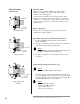
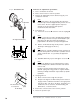
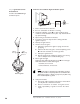
Bypass Start Gas Piping (optional)
Install the piping as shown in the schematics referred to in
Chapter 3 of the RatioMatic Design Guide No. 110 using the
following guidelines.
•
Locate the start gas solenoids 1 close to the burner.
The gas must reach the burner during the trial for
ignition period.
• Minimize piping elbows.
• Install an adjustable limiting orifice (ALO) 2 for start gas
adjustment. Refer to Bulletin 728 and 730 for further
information.
•
Include a straight run of pipe at least 8 inches long 3 before
(upstream from) the start gas orifice 5 (optional) and at least
4 inches long 4 after (downstream from) the start gas orifice.
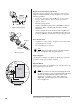
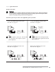
Pipe Connections
• Installation of a pipe union in the gas line is recommended
to simplify burner removal.
• Use of flexible pipe is optional.
Note:
Flexible pipe causes higher pressure drops than standard
pipe. Consider this when sizing your gas lines.
Piping Support
Use brackets or hangers to support the gas piping. If you have
questions, consult your local gas company.
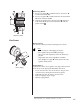
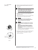
Control Motor
Install a control motor to modulate the air butterfly valve if not
previously installed on the burner.
Note:
Be sure the control motor shaft and air butterfly valve shaft
are aligned properly. If using an Eclipse Actuator Mounting
Parts Kit, the supplied washers may be used as shims
(stacked 0, 1, or 2 high) to ensure proper alignment.
Additionally, a flexible coupling can be used to handle
minor misalignment.
Bracket
Pipe
Union
Control Motor
Pipe Connections
Main gas
shut-off
valve train
NC
4
3
2
1
5
NC
Bypass Start Gas Piping
Set
Screws
Motor
Shaft
Control
Motor
Coupling
Washers
BV
Shaft