
Installation guide


Eclipse RatioMatic v3.10 - Installation Guide No. 110, 7/1/03
13
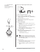
GAS PIPING
NOZZLE
POSITION
2
9
10
11
8
7
1
4
Refractory Block
Refractory Block
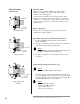
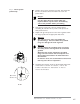
1. Be sure the gasket n is installed between the burner q
and the block holder t.
2. Be sure the gasket u is installed between the block holder
t and the chamber wall o.
3. Support the weight of the refractory block v with hard
brick work w. Fill space around the block v with soft
gasket material .
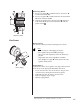
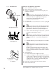
Burner Piping
The burner is factory assembled and shipped as ordered.
Note:
If it is necessary to redirect piping, be sure the:
•ratio regulator spring column n is pointing up.
•
arrow on the ratio regulator points in the direction of
gas flow
.
• integral fuel orifice and o-rings o are re-installed.
• same straight run of pipe p remains between the ratio
regulator and the burner .
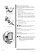
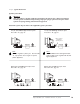
Supply Piping
Inlet pressure to the ratio regulator must stay within specified
limits. Refer to the appropriate RatioMatic data sheet.
• Locate the valve train close to the burner. The gas must
reach the burner during the fixed trial for ignition.
• Sufficiently size shut off valves in the valve train.
• Make sure piping is large enough.
• Minimize piping elbows.
11
Burner Piping