
Installation guide


Eclipse RatioMatic v3.10 - Installation Guide No. 110, 7/1/03
12
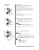
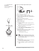
Fiber insulation
Chamber
insulation
NOZZLE
POSITION
1
4
2
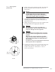
Chamber Wall
Make sure the chamber wall o is strong enough to
support the weight of the burner q. If necessary,
reinforce the mounting area.
I
f the chamber insulation extends beyond the nozzle
position of the burner, taper the insulation around the
combustor at a minimum 45° angle. Refer to data sheets
to determine the position of the nozzle relative to the
chamber wall.
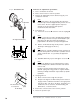
Burner Mounting
Mount burner to chamber wall using four (4) customer
supplied nuts and lock washers.
Both Alloy and Silicon Carbide (SiC) Combustor
1. Be sure gasket n is installed between burner q and
chamber wall o.
2. Pack fiber insulation around the combustor to a depth not
beyond the nozzle position, as illustrated.
Caution:
Placing insulation around the combustor beyond the burner
nozzle position will decrease combustor life.
3. No gasket is supplied or required between burner and
combustor.
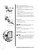
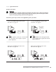
Silicon Carbide (SiC) Combustor only
Caution:
SiC combustor 5 is fragile. Handle with care.
If the SiC combustor is not already attached to the burner,
be sure gasket p is installed between the SiC combustor r
and flange s. Tighten the screws which hold the flange s to
the burner 4 evenly. Do not over tighten.
Caution:
When replacing SiC combustor:
• be sure gasket p is installed
• tighten screws evenly
• do not use excessive force
Alloy Combustor
INSTALLATION
(CONTINUED)
NOZZLE
POSITION
4
2
45 Minimum
Chamber
insulation
NOZZLE
POSITION
1
3
5
6
4
2
Fiber insulation
Chamber
insulation
Silicon Carbide (SiC)
Combustor
Chamber Wall