Installation Guide No.110 7/1/03 RatioMatic Burners RM Series Version 3.
COPYRIGHT Copyright 2003 by Eclipse, Inc. All rights reserved worldwide. This publication is protected by federal regulation and shall not be copied, distributed, transmitted, transcribed or translated into any human or computer language, in any form or by any means, to any third parties, without the express written consent of Eclipse, Inc., Rockford, Illinois, U.S.A.
About this manual AUDIENCE This manual has been written for people who are already familiar with all aspects of a nozzle-mix burner and its add-on components, also referred to as “the burner system.” These aspects are: • installation • use • maintenance. The audience is expected to have had experience with this kind of equipment. RATIOMATIC DOCUMENTS Installation Guide No.
DOCUMENT CONVENTIONS There are several special symbols in this document. You must know their meaning and importance. The explanation of these symbols follows below. Please read it thoroughly. Danger: Indicates hazards or unsafe practices which WILL result in severe personal injury or even death. Only qualified and well trained personnel are allowed to carry out these instructions or procedures. Act with great care and follow the instructions.
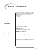
Table of Contents About this manual . . . . . . . . . . . . . . . . . . . . . . . . . . Audience . . . . . . . . . . . . . . . . . . . . . . . . . . . . . . . . . . . . RatioMatic Documents . . . . . . . . . . . . . . . . . . . . . . . . . Related Documents . . . . . . . . . . . . . . . . . . . . . . . . . . . . Document Conventions . . . . . . . . . . . . . . . . . . . . . . . . How to Get Help . . . . . . . . . . . . . . . . . . . . . . . . . . . . . 3 3 3 3 4 4 Table of Contents . . . . . . . . . . . .
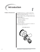
Introduction PRODUCT DESCRIPTION 1 The RatioMatic Version 3.10 is a nozzle-mix type burner designed for direct air heating, indirect air heating, and oven applications up to 1800° F. (1000° C.) The burner package includes a combustion air blower and an air:gas ratio regulator to fire over a wide gas turndown range at a controlled ratio.
Safety INTRODUCTION SAFETY 2 This section is provided as a guide for the safe operation of the RatioMatic burner system. All involved personnel should read this section carefully before operating this system. Danger: The RatioMatic burners, described herein, are designed to mix fuel with air and burn the resulting mixture. All fuel burning devices are capable of producing fires and explosions if improperly applied, installed, adjusted, controlled, or maintained.
CAPABILITIES 8 Only qualified personnel, with good mechanical aptitude and experience with combustion equipment, should adjust, maintain, or troubleshoot any mechanical or electrical part of this system. OPERATOR TRAINING The best safety precaution is an alert and trained operator. Train new operators thoroughly and have them demonstrate an adequate understanding of the equipment and its operation.
Installation INTRODUCTION HANDLING AND STORAGE 3 In this chapter you will find information and instructions needed to install the burner and system components. Handling Inspect the system, being sure the components are clean and free of damage. Use the appropriate support and handling equipment when lifting the burner. Protect all components on the system from weather, damage, dirt and moisture. Protect the system and its components from excessive temperatures and humidity.
Gas piping All gas piping must comply with all applicable local codes and/ or standards, which may include: • NFPA Standard 54 • ANSI Z223 • EN 746-2 Where to get the standards The NFPA Standards are available from: National Fire Protection Agency Batterymarch Park Quincy, MA 02269 The ANSI Standards are available from: American National Standard Institute 1430 Broadway New York, NY 10018 The UL Standards are available from: 333 Pfingsten Road Northbrook, IL 60062 The FM Standards are available from: 1151 B
PRE-INSTALLATION CHECKLIST Air Supply Provide an opening in the burner room of at least one square inch per 4000 BTU/hr (6 cm2 per 1 kW) to supply the burner intake with fresh, outdoor, combustion air. If there are corrosive fumes or materials in the surrounding air, find an uncontaminated source to supply air to the burner. Exhaust Do not allow exhaust gases to accumulate in the work area. Provide a means for exhausting these gases from the building.
INSTALLATION (CONTINUED) 4 NOZZLE POSITION 45 Minimum Chamber insulation 2 Chamber Wall Chamber Wall Make sure the chamber wall o is strong enough to support the weight of the burner q. If necessary, reinforce the mounting area. If the chamber insulation extends beyond the nozzle position of the burner, taper the insulation around the combustor at a minimum 45° angle. Refer to data sheets to determine the position of the nozzle relative to the chamber wall.
7 11 1 NOZZLE POSITION 4 Refractory Block 1. Be sure the gasket n is installed between the burner q and the block holder t. 2. Be sure the gasket u is installed between the block holder t and the chamber wall o. 3. Support the weight of the refractory block v with hard brick work w. Fill space around the block v with soft gasket material 11 . 8 2 9 10 Refractory Block GAS PIPING Burner Piping The burner is factory assembled and shipped as ordered.
Main gas shut-off valve train 1 NC 2 NC 4 5 3 Bypass Start Gas Piping Bracket Pipe Union Bypass Start Gas Piping (optional) Install the piping as shown in the schematics referred to in Chapter 3 of the RatioMatic Design Guide No. 110 using the following guidelines. • Locate the start gas solenoids 1 close to the burner. The gas must reach the burner during the trial for ignition period. • Minimize piping elbows. • Install an adjustable limiting orifice (ALO) 2 for start gas adjustment.
CHECK LIST AFTER INSTALLATION To verify the system was properly installed, perform the following checks: 1. Be sure there are no leaks in the gas lines. 2. Be sure all the components contained in the flame monitoring and control system are properly installed. This includes verifying that: • all the switches are installed in the correct locations. • all wiring, pressure, and impulse lines are properly connected. 3. Be sure all components of the spark ignition system are installed and functioning properly.
Adjustment, Start & Stop INTRODUCTION 4 In this chapter, you will find instructions on how to adjust, start, and stop the burner system. Become familiar with burner control methods before attempting to make adjustments.. Danger: The RatioMatic burners, described herein, are designed to mix fuel with air and burn the resulting mixture. All fuel burning devices are capable of producing fires and explosions if improperly applied, installed, adjusted, controlled, or maintained.
Step 1: Reset system (continued) 5. Activate the pressure switches and other limit interlocks. Be sure the switches fail as intended in the event of a power failure. Danger: If simulated limits or simulated flame failures do not shut down the fuel system within the required failure response time, immediately correct the problem before proceeding. 6. If the burner is firing into a duct or chamber with a circulating fan, start the fan to produce a full process air flow past the burner. 7.
Step2: Set low fire air To Chamber Tap C Low fire air adjustment procedure: 1. Start combustion air blower. 2. Drive control motor to low fire position. 3. Measure air differential pressure between tap (C ) and combustion chamber. Note: The pressure tap is in the open position when the screw inside the tap is unscrewed approximately 1/2 turn. Do not remove screw. Be sure to tighten pressure tap screw clockwise to the closed position after pressure measurements have been taken. 4. Set low fire air. a.
Step3: Ignite the burner Ignition procedure: Warning: This procedure is written with the assumption the burner has a flame monitoring control system installed and operating. A proper purge cycle must be part of the system and purge timing should not be bypassed. Determine system layout and use the applicable ignition procedure. Low fire start without high turndown option. Procedure “A”, page 20 Low fire start with high turndown option.
Step3: Ignite the burner Procedure A: Low fire start without high turndown option. Low fire start without high turndown option: Main gas shut-off valve train CW for more gas Bias Adjusting Screw Ratio Regulator 1. Drive control motor to low fire. 2. Be sure combustion air blower is running. 3. Verify bias adjusting screw 1 on ratio-regulator spring column is six full clockwise turns (360° x 6) down from the top (initial setting). 4. Open main gas manual shut off valves. 5.
Step3: Ignite the burner Procedure B: Low fire start with high turndown option. Low fire start with high turndown option: Ratio regulator with bypass adjusting screw Main gas shut-off valve train 1. 2. 3. CW for more gas Bias 1 adjusting screw CCW for more gas 2 Internal bypass adjusting screw Ratio Regulator (with internal bypass adjusting screw) Drive control motor to low fire. Be sure combustion air blower is running.
Step3: Ignite the burner Procedure C: Bypass start gas without fuel orifice meter. Bypass start gas without fuel orifice meter: 3 Main gas shut-off valvetrain 2 NC NC 1 1. 2. 3. 4. 5. 6. ALO 3 Adjusting Screw CCW for more gas Cap Adjustable Limiting Orifice (ALO) Drive control motor to low fire. Be sure combustion air blower is running. Be sure main gas manual shut off valves are closed. Open manual shut off valve 1 in the bypass. Set the system to operate on bypass gas only.
Step3: Ignite the burner Procedure D: Bypass start gas with fuel orifice meter Bypass start gas with fuel orifice meter: Main gas shut-off valve train 3 1. 2. 3. 4. 5. 6. 7. 8. 9. Adjustable Limiting Orifice (ALO) NC 2 NC 4 1 Drive control motor to low fire. Be sure combustion air blower is running. Be sure main gas manual shut off valves are closed. Prepare to measure bypass gas flow at the fuel orifice meter 4. Open manual shut off valve 1 in the bypass.
Step 4: Set low fire gas (Only required if bypass start is used.) Set low fire gas procedure: Warning: This procedure is written with the assumption the burner has a flame monitoring control system installed and operating. A proper purge cycle must be part of the system control and purge timing should not be bypassed. This step is only necessary when bypass start gas is used.
Step4: Set low fire gas (continued) 1 Bias adjusting screw CW for more gas CCW for more gas 2 Internal bypass adjusting screw Ratio Regulator (with internal bypass adjusting screw) Bypass start gas with high turndown option: 1. Verify bias adjusting screw 1 on ratio regulator spring column is six full clockwise turns (360° x 6) down from the top (initial setting). 2. Open all manual shut off valves. 3. Close internal bypass adjusting screw 2 by turning it clockwise to closed position. 4.
Step5: Verify Settings Setting verification: Note: There are no high fire gas adjustments or air adjustments when firing into a neutral chamber. However, air and gas pressures can be used to verify the burner system is properly adjusted. Tap C Chamber Tap D Tap B 1. With burner lit, drive control motor to high fire. 2. Wait for the chamber to reach normal operating conditions (e.g. chamber temperature, process flows, etc.). 3. Measure high fire fuel differential pressure between tap (B) and tap (D).
Maintenance & Troubleshooting INTRODUCTION 5 This chapter is divided into two sections: • Maintenance procedures • Troubleshooting guide Preventive maintenance is the key to a reliable, safe and efficient system. The core of any preventive maintenance system is a list of periodic tasks. MAINTENANCE Monthly Checklist Note: These are guidelines only. The customer should make the final determination on maintenance intervals and tasks to be performed while considering the working environment. 1.
Yearly Checklist 1 4 28 1. Leak test the safety shut-off valves for tightness of closure. 2. Test the pressure switch settings by checking the switch movements against pressure settings and comparing these with the actual impulse pressure. 3. Visually check igniter cable and connectors. 4. Inspect impulse piping for leaks. 5. Remove, clean, and inspect all burners. 6. Remove and clean the orifice plate 4 . 7. Be sure the following components are not damaged or distorted: • the burner nozzle.
TROUBLESHOOTING PROCEDURES PROBLEM Start-up sequence runs but burner does not light. POSSIBLE CAUSE SOLUTION No ignition: • There is no power to the ignition transformer. No ignition: • Open circuit between the ignition transformer and the igniter. No ignition: • The igniter needs cleaning. No ignition: • The igniter is not correctly grounded to the burner. Restore the power to the ignition transformer. No ignition: • Igniter insulator is broken. Igniter is grounding out.
PROBLEM Start-up sequence runs but burner does not light. (continued) The low fire flame is weak or unstable. The burner goes out when it cycles to high fire. 30 POSSIBLE CAUSE SOLUTION No flame signal: •Broken flamerod •Dirty UV scanner lens Inspect and clean sensor Replace if necessary No flame signal: • Spark plug and flamerod reversed Exchange spark plug/flamerod or their wiring Too much gas: • Wrong or missing burner fuel orifice.
PROBLEM Cannot initiate a start sequence. POSSIBLE CAUSE SOLUTION • Air pressure switch has not made contact. Check air pressure switch adjustment. Check air filter. Check blower rotation. Check outlet pressure from blower. • High gas pressure switch has activated. • Low gas pressure switch has activated. Check incoming gas pressure. Adjust gas pressure if necessary. Check pressure switch setting and operation. • • Malfunction of the flame safeguard system (e.g.
Appendix CONVERSION FACTORS Metric to English. From To 3 Multiply By 3 cubic meter (m ) cubic foot (ft ) 35.31 cubic meter/hour (m /h) cubic foot/hour (cfh) 35.31 degrees Celsuis (ºC) degrees Fahrenheit (ºF) (ºC x 1.8) + 32 kilogram (kg) pound (lb) 2.205 kilowatt (kW) BTU/hr 3414 meter (m) foot (ft) 3.28 millibar (mbar) inches water column (“w.c.) 0.401 millibar (mbar) pounds/sq in (psi) 14.5 x 10⁻³ millimeter (mm) inch (in) 3.94 x 10⁻² MJ/m3 (normal) BTU/ft3 (standard) 2.
KEY TO SYSTEM SCHEMATICS Symbol Appearance These are the symbols used in the schematics. Name Remarks Bulletin/ Info Guide RatioMatic NC Main Gas Shutoff Valve Train Eclipse Combustion, Inc. strongly endorses NFPA as a minimum Gas Cock Gas cocks are used to manually shut off the gas supply on both sides of the main gas shut-off valve train. 710 Solenoid Valve (normally closed) Solenoid valves are used to automatically shut off the gas supply on a bypass gas system or on small capacity burners.
KEY TO SYSTEM SCHEMATICS (CONTINUED) Symbol Appearance Name Remarks Pressure Taps Impulse Line 34 Eclipse RatioMatic v3.10 - Installation Guide No.
Offered By: Burnerparts.com 2011 Williamsburg Road Richmond, Virginia 23231 Phone (804) 236-3881 Fax (804) 236-3882 www.burnerparts.