Standalone Digital Video Recorder Premium DVR 4, 8, 16 Channel Models User`s Manual This document contains preliminary information and is subject to change without notice.
FCC Compliance Statement Notice to Users: This equipment has been tested and found to comply with the limits for a Class A digital device. Pursuant to Part 15 of the FCC Rules, these limits are designed to provide reasonable protection against harmful interference when the equipment is operated in a commercial environment.
Caution This product has free voltages (100V ~ 240V). See installation instructions before connecting to the power supply. This product uses a Lithium battery. To avoid any risk of explosion, do not replace the battery on the main board by anything other than a Lithium battery. Dispose of used batteries according to the manufacturer’s instructions. This equipment and all communication wirings are intended for indoor use only.
parts that could result in a fire or electric shock. Never spill liquid of any kind on the equipment. 12. Servicing Do not attempt to service this equipment yourself. Refer all servicing to qualified service personnel. 13. Damage Requiring Service Unplug this equipment from the wall outlet and refer servicing to qualified service personnel under the following conditions: ① When the power-supply cord or the plug has been damaged. ② If liquid is spilled or objects have fallen into the equipment.
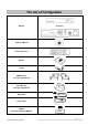
The List of Configuration IQ-SDI-4 (Mini) : 4CH DVR Set IQ-SDI-8/16 Manual / CMS CD Remote Controller Manual Screws HDD Brackets (Except A Type Model) Rack Bracket (Except A Type Model) Data Cable Power Cable Adapter (Except D and E Type Models) Ness IQ-SDI Users Manual 5|Page
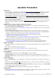
Operation Precautions Power Off Do not turn DVR off, or plug off the power adapter while DVR is in operation (record/playback). Otherwise, it may cause permanent damage to the equipment. Please click ( ) SETUP>SYSTEM>Shutdown sequentially and then remove the power after DVR is shutdown completely. It is safe to wait for 5 seconds before turning the power on again. Do not turn DVR off, or plug off the power adapter while External storage device (e.g.
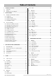
Table of Contents 1. PRODUCT FEATURES ..................................................9 1.1 Unpacking....................................................................9 1.2 Service.........................................................................9 4.3.5 VGA ....................................................................... 32 4.4 1.3 System Connection Diagram.......................................9 2. INSTALLATION ............................................................11 2.1 4.4.
NOTES : Ness IQ-SDI Users Manual 8|Page
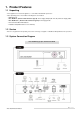
1. Product Features 1.1 Unpacking This equipment is an electronic appliance, so it should be handled with special care. After unpacking, please check if all the following items are included. - DVR Main body - Ness IQ-SDI-4 (Known in this manual as Type A): Power Supply Adapter (DC 12V, 5A) and Power Supply Cable - Ness IQ-SDI-8/16 (Known in this manual as Type B): Power Supply Cable - Remote Control With 2 AAA batteries - Installation CD (CMS Software & User’s Manual) 1.
Ness IQ-SDI-8/16 (Type B) 8 / 16 channel Series HD- Ness IQ-SDI Users Manual 10 | P a g e
2. Installation 2.1 Hard disk and DVD-RW Installation 2.1.1 SATA Port Ness IQ-SDI-4 - Main substrate of this DVR has one SATA port: it is indicated as SATA 1. - Only one SATA device (hard disk) is possible to connect in Serial to the SATA port. Ness IQ-SDI-8/16 - Main substrate of this DVR has five SATA ports: they are indicated as SATA 1, 2, 3, 4 and SATA 5. - Please mount DVD-RW at the SATA port 5. Ness IQ-SDI – 4 Mini (Ness Part No.
2.1.2 HDD Installation Securely fix a hard disk by using bracket and screws provided herewith. Please do not use any different hard disk cables (data cable and power supply cable) other than ones we provide. Otherwise, it may cause damage to the hard disk. CAUTION INSTALL HARD DISK AGTER DVR POWER IS OFF. OTHERWISE, IT MAY CAUSE PERMANENT DAMAGE TO THE HARD DISK. TO TURN OFF DVR, PLEASE CLICK ( ) SETUP>SYSTEM>SHUTDOWN. ALSO, WAIT FOR 5 SECONDS BEFORE PLUGGING IN POWER SUPPLY AGAIN.
Connect cameras to ‘HD-SDI IN’ to channel 1 to 16. 2.2.2 HD-SDI Camera Input Format HD-SDI recorder shall recognize following HD-SDI signals - 720P 24, 720P 25, 720P 30, 720P 50, 720P 60, 1080I 50, 1080I 60, 1080P 24, 1080P 25, 1080P 30, 1080P 50 and 1080P 60. 2.2.
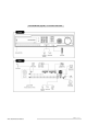
2.2.7 TCP/IP(Ethernet) Connections Connect to ‘ETHERNET’ connector with the LAN cable. When connect to Internet, use an ordinary LAN cable (Non-cross cable). However, when connect directly to a PC, please use only ‘Crossover cable’. 2.2.8 Alarm Connections Connect Alarm Input (Sensor) to ‘AI 1~AI 2 (or AI 16)’ connectors and connect Sensor Common to ‘G’ connector. Connect Alarm Output (buzzer, siren, etc.) to ‘AO 1~AO 2 (or AI 16)’ connectors and connect Common to ‘G’ connector.
Ness IQ-SDI 8/16 : Plug the power supply adapter (DC 12V, 6.67A) which include in this product to ’DC12V’ connector and plug another side to power source. Adapter input voltage is a free volt (100 VAC ~ 240 VAC). Please do not use any different power supply adapter because it may cause the DVR to malfunction. AC powered DVR: Plug the power supply cable into the power supply (the wall socket). Input voltage is a free volt (100 VAC ~ 240 VAC). 2.2.
3. Input Device and Screen Icons 3.
3.2 Camera Select Keys for 16 Channel DVR Ness IQ-SDI 8/16 Below shows how to select camera channel for 8/16channel DVR Type has a Menu key and direction keys in the front. Below shows how to select camera channel for 8 channel DVR - Select Camera No. 1~8 Below shows how to select camera channel for 16hannel DVR - Select Camera No. 1~16: press key and use 1~6 direction key NOTE A Type no camera select button at front. Please use an ir remote control or mouse to control the channels. 3.
3.5 Using a Mouse Mouse provides an easier access to adjustment. Refer to below for proper use. Left mouse button functions the same as Enter ( ) key on the front panel of DVR. Right mouse button displays the following “Function keys” on screen. Click Search menu at “Function Keys” the same as Search key on the front panel of DVR. Press the button, then the Search menu will appear on screen.
4. Setup 4.1 Login / Logout At the default setting of DVR, user has to input the password to enter the set up menu. Please press SETUP key to enter the setup menu and the following screen will appear. In order to use all functions and privileges, log in as ID: admin. Default Password is “1111”. At Setup>System>Account, Administrator should set a user rights depending on each user separately in “Login Settings”. After login successfully, following screen will appear.
4.2 SYSTEM 4.2.1 Information Please click ( ) SYSTEM>Information and the following screen will appear. Status Site Description Input the name of DVR. ) keyboard icon on Site Description frame and the following virtual keyboard will appear. Please click ( Please click ( ) desired letters (characters) on the virtual keyboard to input. Use to erase one character every time. Use to erase the whole sentence. Please choose ‘OK’ to confirm the input and choose ‘Cancel’ to cancel.
NOTE This has a different function from Factory Reset Switch on the back panel of DVR in that System Log is not initialized. Import: Copy the Menu setup stored in USB memory stick into DVR. Please plug in the memory stick and then click ( ) Import. Export: Store the Menu setup of DVR in USB memory stick. Please plug in the memory stick and then click ( ) Export.
The screen shows start time and end time of recorded data. Overwrite Setting Click ( ) Overwrite Setting button and the following screen will appear. User shall designate the total recording days from 1 day to 30 days and unlimited. User may set for beeping or notifying messages that notify the used percentage of disk. Check Disk Overwrite and user may activate the overwrite function. - This function makes restart the recording from the beginning when the HDD is full.
④ When all data are deleted, a dialogue box asking “Are you sure to remove log?” will pop up. ⑤ Choose ‘OK’ to delete all the recorded data as well as System Log. When user finished all the necessary inputs to SYSTEM menu, please click ( ) ‘OK’ on the bottom to go back to SETUP screen. NOTE This might take a while to completely delete all data, and DVR will reboot after the data is cleared. 4.2.2 Admin Please click ( ) SYSTEM>Admin and the following screen will appear.
Adjust the dates of beginning (Begin) and end (End) of DST by ‘Month/Week/Weekday’. Click ( ) the numbers in ‘Month/Week/Weekday’ for adjustment. Choose ‘OK’ to confirm the setting. Date Format Set date indication format. Please click ( ) Date Format frame to select a format from the list. Time Format Set time indication format. Please click ( ) Time Format frame to select a format from the list.
Interval Set clock-update-interval from NTP Server. Normally, user can adjust 1 hour up to 24 hours. System Clock Display DVR clock. Server Clock Display NTP Server’s clock if Internet is connected to Server Clock. If not displaying, please click ( ) Connect button. When Server Clock is displayed, please click ( ) Sync button to synchronize NTP Server’s clock with DVR clock. Choose ‘OK’ to confirm the clock synchronization.
S.M.A.R.T Setup Please click ( ) S.M.A.R.T Setup and the following screen will appear. Check the square box next to Use On. Through S.M.A.R.T function, make alarm message, indicating HDD damage, will show. Check Beep; it will give the alarm sound, indicating HDD damage, as the SMART setup. Check Blink Message, the alarm message will blink on the OSD, as the SMART setup. If “Use on” box is unchecked, Beep, Blink Message will be unchecked automatically.
Click ( ) keyboard icon on the right-hand side of Group Name frame. Then, the virtual keyboard will show. Please click ( ) desired characters (up to 8 characteristics) on the virtual keyboard. Do provisioning for Group Name by selectively checking some of the following items (Setup, Search, Network, Archiving and Shut Down). Choose ‘OK’ to confirm the setting. Login Setting Please click ( ) Login Settings and the following screen will appear.
Choose ‘OK’ to confirm the setting. Then, lists of Group and User will show as follows. Click ( ) to delete the set Group or User. User may create up to 8 Groups and 8 Users. Choose ‘OK’ to confirm the setting. Password Resetting Click ID on User column. The following screen will appear. This is a screen for password resetting. Input password by clicking the keyboard icon on the right-hand side of the frame.
Use 4.2.4 key if wish to erase password on keyboard. System Log Please click ( ) SYSTEM>System Log and the following screen will appear. System Log displays diverse events as below events by specifying the user account that actually has accessed the DVR. - Setup (Menu) Enter/Exit - Playback Mode Enter/Exit - Network Access Enter/Exit - Archive Success/Fail - System Start/shut down - S.M.A.R.T.
CAUTION ANY CHANGES MADE IN SETUP ARE APPLIED AFTER EXIT. 4.2.6 Shutdown Shutdown is a function to help user safely turn the DVR off. Please use the proper shut down procedure to avoid damaging to our DVR system. Do not remove the power during shut down. CAUTION DO NOT TURN DVR OFF WITHOUT USING THE PROPER SHUT DOWN PROCEDURE. OTHERWISE, IT MAY CAUSE DAMAGE TO DVR. ALWAYS REMOVE THE POWER AFTER SHUT DOWN. ) SYSTEM>Shutdown and then choose ‘OK’ on the dialogue box to confirm.
dropped out and invisible on the monitor. Adjust Horizontal to change margin between both ends of the monitor on horizontal side and OSD. Margin range is between 0 and 50, with a larger number representing greater margin. Adjust Vertical to change margin between both ends of the monitor on vert 130. Vertical side and OSD Margin range is between 0 and 50, with a larger number representing greater margin. While pressing (+) or (-) button, a target value increases or decreases by 10 units.
4.3.3 VGA Users are able to set its video output resolution from 1024x768 to 1920x1080 If user wishes to hear audio via HDMI cable, check the box HD Audio Output HD-SDI DVR displays and records differently with previous NTSC or PAL methods.
LAN Network Type Please click ( ) Network Type. When you click ( ) the button, it changes alternately to Static (fixed IP) and DHCP (floating IP). In Static, user must manually set the static IP address for use. - Set IP Address, Subnet Mask and Gateway. Please ask your network administrator for more details. - To input address, please click ( ) and execute the keyboard icon on the right-hand side of each frame.
‘Floating IP system’, although being predominantly used over Internet, is very inconvenient for users because its address varies every time when user access. The best alternative is DDNS (Dynamic Domain Naming System) which uses name (domain name) instead of IP address (numbers). DDNS automatically recognizes ever changing, floating IP addresses, so it will allow easy Internet access. Dvrdormain.com - Check a checkbox of Dvrdomain.com to use Dvrdomain.com Server. - As for DDNS Server, Dvrdomain.
Network Throat is for setting an average transfer speed. Please choose the suitable speed according to the users’ network environment. If users want to use dual streaming, please click on the check box beside the “Enable Dual Streaming”. If not, please uncheck the check box. There are various network throat controls which users may choose. - Ethernet support Max. 1000Mbps. Network video transmission speed and quality can be configured by pressing “Frames” and “Quality” buttons as follows.
The Notification menu allows sending users the message of the Event occurred in the DVR via E-Mail. Click ( ) the keyboard icon on the right-hand side of Add E-Mail frame and the virtual keyboard will appear. Please register E-Mail address. E-Mail address should contain @. Click ( ) the keyboard icon on the right-hand side of SMTP Server frame and the virtual keyboard will appear. Please register the SMTP Server. SMTP server can be set up by the users to have own SMTP server on their site.
CAUTION WHEN USER EXCLUDES A CORRESPONDING CAMERA VIDEO FROM RECORDING AND MONITOR DISPLAY (CHECK A CHECK BOX ), MAKE SURE CHANNELS OF LARGE NUMBERS ARE EXCLUDED FIRST. If a check box is checked on Covert column, a video is recorded but is not displayed on the monitor. Click ( ) each frame on PTZ column to select PTZ protocols connected to a corresponding camera. Click ( ) each frame on Set to set PTZ Settings connected to a corresponding camera.
not marked, audio is not recorded. If users check on bind to cam, then the audio and video of same channel will come out. If not, the audio of unchecked channel will not come out. In addition, this function will effect on live screen. (The default audio channel is No. 1) Choose ‘OK’ to confirm the setting. 4.4.4 Alarm In Please click ( ) DEVICES>Alarm In and the following screen will appear. The Alarm In menu will allow user to give title and to select the type of Alarm input.
- NC: contact is normally closed (Normally closed) User may change the type and duration of all Alarm output at a time by clicking the Type and Duration box on the menu tab. Choose ‘OK’ to confirm setting. 4.4.6 Serial In NOTE Please refer to “14 Serial In”. 4.5 RECORD Please click ( ) RECORD and the following screen will appear.
4.5.1 Setting Please click ( ) RECORD>Settings and the following screen will appear. There are three kinds of recording mode. - Continuous: record continuously. - Event: record only when Sensor or Motion calls. - Emergency: record when press EMERGENCY key. Continuous The Continuous menu will allow user to set recording mode. Each frame on Title column shows camera title registered in DEVICES>Camera/PTZ. User cannot change camera titles here.
Event Please click ( ) Event and the following screen will appear. The Event menu will allow user to set Event videos. Each frame on Title column shows camera title registered in DEVICES>Camera/PTZ. User cannot change camera titles here. Click ( ) each frame on Resolution column to select recording resolution of a corresponding camera.
Click ( ) each frame on Resolution column to select recording resolution of a corresponding camera. User may select one of 360x 240(288), 720x240(288), 720x480(576), 1280x720 and 1920x1080 Click ( ) each frame on Frames column to select recording rate of a corresponding camera. Recording rate varies by camera. Below lists the maximum recording rate of each camera. Ness IQ-SDI Model 360x 240(288) 720x240(288) 720x480(576) 1280 x 720 1920 x 1080 4 Channel DVR Max. 25 fps per Channel Max.
Repeat the procedure for Camera Nos. 2 to 16. If user wants every camera to have the same mode, please click ( ) Copy to All Camera. Below lists symbols of the respective recording modes. Continuous Alarm In Alarm In / Continuous Alarm In / PreAlarm Motion Motion / Continuous Motion / PreAlarm Motion / Alarm In Motion / Alarm In / Continuous Motion / Alarm In / PreAlarm Choose ‘OK’ to confirm the setting. NOTE Holiday (H) registration is done with a separate menu. 4.5.
Click ( ) each frame on Resolution column to select recording resolution of a corresponding camera. User may select one of 360x 240(288), 720x240(288), 720x480(576), 1280x720 and 1920x1080 Click ( ) each frame on Frames column to select recording rate of a corresponding camera. Recording rate varies by camera. Below lists the maximum recording rate of each camera. Ness IQ-SDI Model 360x 240(288) 720x240(288) 720x480(576) 1280 x 720 1920 x 1080 4 Channel DVR Max. 25 fps per Channel Max.
- Deselect All: deactivate all blocks. - Copy to All Cameras: The present channel setup applies to all other cameras. Only when click save button, the changed setup can be saved. - Save: save the new settings and go back to previous menu (page). - Exit: ignore the new settings and go back to previous menu (page). - Cancel: cancel Motion Setup menu. Choose ‘OK’ to confirm the setting. 4.5.5 Holiday Please click ( ) RECORD>Holiday and the following screen will appear.
4.6.1 Alarm In Please click ( ) LINK>Alarm In and the following screen will appear. Select cameras for recording while the motion sensor is in operation and alarm outputs and set up E-mail addresses for notification. Link Notification displays E-mail addresses registered in DEVICES>Network>Notification. Please follow the setup procedures below. ① Click ( ) Alarm In frame and select Alarm In 1. ② Select cameras for recording when Alarm In 1 is on. Please check a check box under Link Camera.
① Click ( ) Motion Event frame and select Motion Event 1. ② Select cameras for recording when Motion Event 1 is on. Please check a check box under Link Camera. More than two cameras can be set. ③ Select alarm outputs to be worked when Motion Event 1 is on. Please check a check box under Link Alarm Out. More than two alarm outputs can be set. ④ Select E-mail addresses for notification when Motion Event 1 is on. Please check a check box under Link Notification.
Select recording cameras and alarm outputs while Emergency recording using EMERGENCY key and set E-mail addresses for notification. Link Notification displays E-mail addresses registered in DEVICES>Network>Notification. Please follow the setup procedures below. ① System Event frame displays Emergency, which user does not have to change. ② Select cameras for recording when emergency occurs. Please check a check box under Link Camera. More than two cameras can be set.
5. OPERATING INSTRUCTIONS 5.1 Viewing 5.1.1 First Image Power on DVR and the following live video will appear, while viewing and recording at the same time. The screen will display date/time and icons below. Icon Description Continuous recording mode Event recording mode (Alarm In/Motion) In recording PTZ registration/PTZ mode In Audio recording 16 CMS Access Indication/No.
Click Audio button, icon will show. And click channel button, then user can change only audio channel. NOTE When front key does not work well, please check whether the audio icon 5.1.2 is activated on the screen. View Format The available view formats when the Main Monitor is in viewing mode include Full Screen, Split Screen, Channel Sequencing Screen and PIP screen. - Full Screen: Please press camera select key (1~16) to view the corresponding camera image in full view format.
Following is the key usage found in Pan/Tilt mode. Key Function Up/Down/Left/Right rotation Zoom out Zoom in Focus near Focus far Iris Close Iris Open Save Preset Go to the Preset Go to OSD main menu Run Group Tour 1~9 Run Pattern 1~9 To use a mouse in Pan/Tilt mode, please move the cursor to the lower portion near the center of the screen. To use front button in Pan/Tilt mode, please push setup button.
NOTE It is required to set Menu as Preset number 95 from camera in order to call camera menu display by clicking ‘menu’ button or using 95+Goto button. 5.1.6 System Log Press EVENT key and the System Log screen will appear. Please refer ‘SETUP>SYSTEM>System Log’ to learn different events listed on the System Log and see how to delete the System Log. 5.1.7 Key Lock Press AUDIO>FF>FORWARD keys in sequence to operate the key lock function.
There are three ways to search video, i.e., by date/time and by calendar. - Date/Time Search: search by inputting date/time. - Calendar Search: search by using calendar. - Event Search: search by event. 5.2.1 Date / Time Search Please click ( ) Date/Time Search in SEARCH menu and the following input box will appear. Follow the procedure below to search video by date/time. ① Click ( ) the date and/or time whichever user needs to change and block the item.
⑤ The screen will show selected date/time. ⑥ Click ▲▼ button for selecting cameras. ⑦ Click then recorded data will be highlighted on the bar. ⑧ Selected camera will show the time bar 0-60 and It will be marked on 2.5minutes basis during selected time zone. ⑨ Click ( ) the high-lighted box on the time indication bar to select the start time of the video playback Click ( ) Search key to start playing back the selected video.
5.3 Playback This involves searching recorded video to playback the wanted video of a specific date and time in search mode. Press SETUP key or please press the mouse right button and click in Playback mode. Then, the following screen will appear. There are three ways to search video, i.e., by date/time and by calendar. - Date/Time Search: search by inputting date/time. - Calendar Search: search by using calendar. - Event Search: search by event.
5.4 One-touch Playback Press the PLAY/PAUSE key or double click the mouse wheel (central button) in the viewing mode. Then, user will be able to view the wanted recorded video right away without going through the search procedure. The video plays back the recorded video from the last one minute. To stop playing back the video, please press SEARCH key. 5.5 Digital Zoom in Playback Users are able to use Digital Zoon function in full screen playback.
NOTE Please do not use jpeg format selecting while archive in live mode. NOTE Please do not change the settings by DVR or CMS, while back up. NOTE When the target file size is over 2GB, press “ ” button on the right again after the first “ARCHIVE SUCCESS”. And DVR will continue to archive to another file with the extension of “-002” Automatically added. In case of DVD media, change it after the first file is finished and press “ ” to continue to the rest of progress.
Please click (( ) Color / Alarm in SEARCH popup menu or in front panel and the following input box will appear. Choose ‘Close’ to confirm confirm the setting. CAUTION ALTHOUGH USERS TURN ITS SYSTEM SETTING TO DEFAULT, THE ANALOG OUTPUT WILL STAY PREVIOUS OUTPUT METHOD AND NOT EFFECT BY THE DEFAULT SETTING. www.nesscorporation.com HEAD OFFICE Ness Corporation Pty Ltd ABN 28 069 984 372 Phone : +61 2 8825 9222 Fax +61 2 9674 2520 Sydney Ph 02 8825 9222 Fax 02 9674 2520 sales@ness.com.