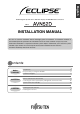
English DVD Navigation System with 7" Wide TFT Display and DVD Multi-Source Receiver MODEL INSTALLATION MANUAL Français Contents Installation 2 3 5 Names and functions of terminals Connecting the vehicle speed pulse, parking brake, and reverse wires System connection example 6 10 12 Installing the GPS antenna Installing the main unit 13 16 Nederlands Connections Components For your safety in using the AVN52D Installation Diagram Italiano Before installation Español Be sure to read this ins
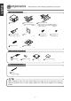
English Components Check that all of the following components are present Main unit components English 1 Main unit x 1 2 Interconnecting wires 3 Interconnecting wires (Power and speaker wires, etc) (16P) x 1 Español 5 Panel 4 Interconnecting wires (Video input) 6 Hex-head bolt x1 (6P) x 1 Français 8 Splicing connector (Sub-woofer, line out, speed pulse, parking brake, reverse, video out and steering remote control connector) (16P) x 1 (Red:M5x8) x 8 7 Flat head screw (Red:M5x8) x 8 9 M
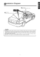
Warnings and caution signs, illustrated below, are posted throughout this manual as well as on the AVN52D. They show safe and correct ways to handle the main unit to prevent personal injury to you and others and avoid damage to property. Before reading through the manual, take time to read through and learn the important information listed in this section.
English • Do not operate the main unit in a malfunctioning condition, for instance, when the audio does not play. Doing so may result in an accident, fire, or electrical shock. • Do not place the vinyl storage bag over a person's head. It may cause a serious accident or death by suffocation. • Do not disassemble or rebuild this main unit. Doing so may cause an accident, fire, or electrical shock.
10 GPS antenna (When installing inside the vehicle) English Installation Diag r am Tip 10 GPS antenna (When installing outside the vehicle) Italiano • If installing the GPS antenna inside the vehicle, the location and the slope of the vehicle's windshield will determine the accuracy of the GPS antenna to receive the GPS signal. If the GPS antenna location inside the vehicle is hindering the accuracy of the GPS antenna, then you may want to install the antenna outside of the vehicle.
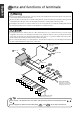
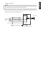
English Name and functions of ter minals • Never cut the insulation on the power wire or use it to power any other equipment. If the rated current capacity of the power wire is exceeded, fire and electric shocks may result. • The wires should be secured with tape or a similar securing method to prevent any obstructions while driving. If they get wound English or entangled around components such as the steering wheel, shifting lever, or brake pedal, accidents may result.
Caution 1 2 , 3 and 4 Never connect the power supply to the speaker wires (No.7 and No.8), otherwise it will cause damage to the main unit. English Wire colors and connection points for connection wires B+ (Yellow) Connect where power is constantly available, regardless of the ignition key's position. 2 ACC (Red) Connect where the power comes on when the ignition is in the ACC position.
English F VTR output terminals Connect to the monitor with video input. G Genuine steering remote control terminal Connect to the vehicle steering remote control. ※ Compatible vehicle models for installation : Vehicles with voltage detection-type steering remote control. Ask your dealer for details. English H VTR input terminals Connect to the output wire of external video main unit such as a VTR.
Tip • You will need to purchase the necessary vehicle component adapter wire for the vehicle so that the power supplies can be utilized. (Contact the dealer for further details.) English - Vehicle connections - • Be sure to wrap the connection wires with electrical tape or another insulation method to insulate them.
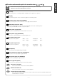
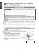
English Connecting the vehicle speed pulse , par king br ak e , and reverse wires Notes on installation English • Check the vehicle speed pulse signal, parking brake signal, and reverse signal carefully before making the connections. If the wires are incorrectly connected, accidents or problems with correct operation may result.
1 Use a splicing connector to connect the parking brake signal wire (red/white) coming from the main unit to the parking brake signal wire of the vehicle. 2 Route the parking brake signal wire to the main unit. English - A connecting the point for parking brake signal (example) Hand-operated parking brake Attach a splicing connector at this location. Parking brake signal wire Parking brake signal wire Foot-operated parking brake Tip • Be sure to connect the reverse signal wire.
English System connection example English • Never cut the insulation on the power wire or use it to power any other main unit. If the rated current capacity of the power wire is exceeded, fire and electric shocks may result. • The wires should be secured with tape or a similar securing method to prevent any obstructions while driving. If they get wound or entangled around components such as the steering wheel, shifting lever, or brake pedal, accidents may result.
Notes on installation English Installing the GPS antenna • The wires should be bound together with tape or a similar securing method (example: wire ties) so that they do not interfere with driving. If it becomes wound or entangled around parts such as the steering wheel, shifting lever, or brake pedal, accidents may result. • Do not install the GPS antenna where it will obstruct the driver's vision or where it will be an obstacle while driving, otherwise traffic accidents may result.
English - Installation inside the vehicle (example) 1 Choose an installation location on the dashboard which is flat and has a clear view of the sky. Tip 12 Ground plate 10 GPS antenna English • Select a location that is at least 20 in. away from the main unit. If this is not done, the GPS measurement precision will drop. • Be sure to use the ground plate when installing the GPS antenna.
1 Choose an installation location where the GPS antenna can be attached securely. 2 Remove the backing paper from the body protective sheet and attach the sheet to the vehicle. 3 10 GPS antenna English - Installation outside the vehicle (example) - 13 Body protective sheet (clear) Install the GPS antenna on top of the body protective sheet. Front of vehicle 5 Route the GPS antenna wire inside the vehicle's trunk and secure it with tape.
English Installing the main unit - Installation angle - Tip English To maintain proper function, the main unit must be mounted less than 30 degrees. If the angle is in excess of 30 degrees, DVD skipping and improper DVD ejection may occur.