by FUJITSU TEN 6.5" Wide TFT Touch-Panel Display CD / DVD Multi-Source Receiver with DVD NAVIGATION MODEL INSTALLATION MANUAL Be sure to read this installation manual thoroughly before carrying out installation and making connections. If installation methods or non-standard parts that are not specified in this installation manual are used, accidents or injury may result. Professional installation is recommended, contact the place of purchase to schedule an appointment.
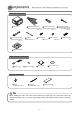
Components Check that all of the following components are present Main unit components 2 Interconnecting cable 1 Main unit x 1 (Power and front speaker connector) (10P) x 1 5 Interconnecting cable 6 Antenna (Video input connector) (6P) x 1 3 Interconnecting cable 7 Hex-head bolt extension cable x 1 4 Interconnecting cable (Speed pulse parking brake and reverse signal connector) (5P) x 1 (Rear speaker connector) (6P) x 1 8 Flathead screw (M5x8) x 8 (M5x8) x 8 9 Splicing connector x3 10 MA
For y our safety in using the AVN2454 Warnings and caution signs, illustrated bellow, are posted throughout this manual as well as on the AVN2454. They show safe and correct ways to handle the product so as to prevent personal injury to you and others and avoid damage to property. Before reading through the manual, take time to read through and learn the important information listed in this section.
• This unit is intended for operation in DC 12volt, • Do not operate the product in a malfunctioning negative-grounded vehicles only. Never use it in 24volt vehicles such as heavy trucks or diesel cars with cold-region specifications. condition, for instance, when the audio does not play. Doing so may result in an accident, fire or electrical shock. • Do not place the vinyl storage bag over a person.
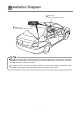
Installation Diag r am 11 GPS antenna (When installing inside the vehicle) Tip 11 GPS antenna (When installing outside the vehicle) 1 Main unit Tip • If installing the GPS antenna inside the vehicle, the location and the slope of the vehicle's windshield will determine the accuracy of the GPS antenna to receive the GPS signal. If this occurs you may want to install the antenna outside of the vehicle.
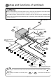
Names and functions of ter minals • Never cut the insulation on the power cable or use it to power any other equipment. If the rated current capacity of the power cable is exceeded, fire and electric shocks may result. • The cables should be secured with tape or similar so that they will not cause an obstruction while driving. If they get wound around components such as the steering wheel, shifting lever or brake pedal, accidents may result.
Wire colors and connection points for connection cables Caution 1 2 and 3 Never connect the power supply to the speaker leads (No.6 and No.7), otherwise it will cause damage to the main unit. B+ (Yellow) Connect where power is constantly available, regardless of the ignition key's position. 2 ACC (Red) Connect where the power comes on when the ignition is in the ACC position. 3 Illumination power supply (Orange/White) Connect to where power comes on when the vehicle light switch is turned on.
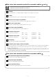
Main unit connections A E-LAN terminal (13P) Connect to the E-LAN terminal of the CD changer, etc. B Genuine steering remote control terminal Connect to the vehicle steering remote control. ※ Compatible vehicle models for installation : Vehicles with voltage detection-type steering remote control. Ask your dealer for details. C VIDEO OUT terminal (Yellow) D Front line-out terminal Connect to a monitor with video input. Connect to the RCA connector of an external amplifier.
Connecting the vehicle speed pulse signal, par king br ak e cab le and reverse cab le Notes on installation • Check the vehicle speed pulse signal, parking brake signal and reverse signal carefully before making the connections. If the cables are incorrectly connected, accidents or problems with correct operation may result.
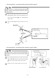
- An example for connecting the parking brake signal - Tip Always be sure to connect the parking brake signal cable, otherwise the measurement precision will be greatly reduced. 1 Use the splicing connector to connect the parking brake signal connector (red/white) of the interconnecting cable 4 to the parking brake signal cable. 2 Route the parking brake signal cable to the main unit.
- Using the splicing connector 1 Insert the connection cable 4 [vehicle speed pulse signal cable (purple/white), parking brake cable (red/white) or reverse cable (green)] and the vehicle cable into the splicing connector. 4 Interconnecting cable Vehicle speed pulse signal cable (purple/white), parking brake cable (red/white) or reverse cable (green) Harness in the car 2 Push in the terminal (the metal part) of the splicing connector using a pair of pliers.
System connection example • Never cut the insulation on the power cable or use it to power any other equipment. If the rated current capacity of the power cable is exceeded, fire and electric shocks may result. • The cables should be secured with tape or similar item so it will not cause an obstruction while driving. If they get wound around components such as the steering wheel, shifting lever or brake pedal, accidents may result.
Installing the GPS antenna Notes on installation • The cables should be bound together with tape or similar so that they do not interfere with driving. If it becomes wound around parts such as the steering wheel, shifting lever or brake pedal, accidents may result. • Do not install the GPS antenna where it will obstruct the driver's vision or where it will be an obstacle while driving, otherwise traffic accidents may result.
- Installation inside the vehicle (example) 1 Choose an installation location on the dashboard which is flat and has a clear view of the sky. Tip 13 Ground plate 11 GPS antenna Select a location that is at least 19.68 in. away from the main unit. If this is not done, the GPS measurement precision will drop. 2 Install the ground plate to the dashboard. 3 Install the GPS antenna to the ground plate.
- Installation outside the vehicle (example) 1 Choose an installation location where the GPS antenna can be attached securely. 11 GPS antenna 2 Remove the backing paper from the body protective sheet and attach the sheet to the vehicle. 3 Install the GPS antenna on top of the body protective sheet. 14 Body protective sheet (clear) Front of vehicle 4 5 Route the GPS antenna cable inside the vehicle's trunk and secure it with clamps.
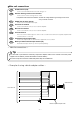
Installing the main unit - Installation angle - Tip To maintain proper function, the unit must be mounted less than 30 degrees. If the angle is in excess of 30 degrees, DVDs, CDs, skipping and improper DVD, CD and Memory Stick ejection may occur. Front 30˚ or less Level (reference) - Mounting the main unit (example)- Tip Connect all cables before installing the main unit.