® INNOVATION IN MOBILITY ™ ECLIPSE F8000 (A) Series Export Use Wheelchair and Standee Lift ® PRINT Service/Owner Manual (To be retained by Owner After Installation by Authorized RICON Dealer) 06/19/98 32DF8AE0.C U.S. Patent # 5,253,973 GB (U.K.) Patent # 2,224,992 Other U.S. and foreign patents pending ©1997-8 RICON CORP.
This RICON product must be installed and serviced only by authorized RICON dealers. The authorized RICON dealer must refer to this manual for installation instructions. The owner must refer to this manual for operating instructions, then retain it for future reference by authorized RICON dealers who perform service and repairs.
TRADEMARK ACKNOWLEDGMENTS ©Copyright 1997 thru 1998 by Ricon® Corporation. All rights reserved. No part of this publication may be reproduced, transmitted, stored in a retrieval system, or translated into any language, in any form or by any means, mechanical, optical, electronic, recording, or otherwise, without prior consent from Ricon.
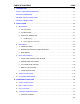
TABLE OF CONTENTS I. PAGE INTRODUCTION . . . . . . . . . . . . . . . . . . . . . . . . . . . . . . . . . . . . . . . . . . . . . . . . . . . . . . . . . . . . . . . . 1-1 RICON 1-YEAR LIMITED WARRANTY . . . . . . . . . . . . . . . . . . . . . . . . . . . . . . . . . . . . . . . . . . . . . . 1-2 DEALERS INFORMATION . . . . . . . . . . . . . . . . . . . . . . . . . . . . . . . . . . . . . . . . . . . . . . . . . . . . . . . . 1-3 GENERAL SAFETY PRECAUTIONS . . . . . . . . . . . . . . . . . . . . . . . . .
2. ELECTRICAL CONTROLS AND INDICATORS . . . . . . . . . . . . . . . . . . . . . . . . . . . . . . . . . . 3-5 a. Main Circuit Breaker . . . . . . . . . . . . . . . . . . . . . . . . . . . . . . . . . . . . . . . . . . . . . . . . . . . . 3-5 b. Control System Circuit Breaker . . . . . . . . . . . . . . . . . . . . . . . . . . . . . . . . . . . . . . . . . . . 3-5 3. MANUAL BACKUP PUMP . . . . . . . . . . . . . . . . . . . . . . . . . . . . . . . . . . . . . . . . . . . . . . . . . . 3-6 a.
LIST OF FIGURES PAGE FIGURE [1-1]: LIFT REFERENCES . . . . . . . . . . . . . . . . . . . . . . . . . . . . . . . . . . . . . . . . . . . . . . . . . . . . 1-4 FIGURE [2-1]: LIFT MOUNTING ATTACHMENT POINTS . . . . . . . . . . . . . . . . . . . . . . . . . . . . . . . . . . 2-1 FIGURE [2-2]: LIFT MOUNTING FASTENER . . . . . . . . . . . . . . . . . . . . . . . . . . . . . . . . . . . . . . . . . . . . 2-2 FIGURE [2-3]: INTERLOCK WIRING . . . . . . . . . . . . . . . . . . . . . . . . . . . . . . . . . . . . .
FIGURE [5-3]: OPTIONAL PUMP ENCLOSURE ASSEMBLY . . . . . . . . . . . . . . . . . . . . . . . . . . . . . . . . 5-6 FIGURE [5-4]: LIFT ENCLOSURE ASSEMBLY . . . . . . . . . . . . . . . . . . . . . . . . . . . . . . . . . . . . . . . . . . 5-10 FIGURE [5-5]: PLATFORM ASSEMBLY . . . . . . . . . . . . . . . . . . . . . . . . . . . . . . . . . . . . . . . . . . . . . . . . 5-14 FIGURE [5-6]: TRAVELING FRAME ASSEMBLY . . . . . . . . . . . . . . . . . . . . . . . . . . . . . . . . . . . . . . . .
NOTES - viii -
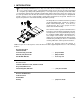
I. INTRODUCTION he RICON Eclipse® F8000 (A) Series Export Use Wheelchair and Standee Lift provides wheelchair access to mass transit vehicles. The patented movement ensures smooth, safe entry and exit and easily lifts up to 660 pounds (300 kilograms). It is designed to be operated by a trained attendant or vehicle driver. After the lift is manually extended OUT (deployed) from the vehicle, the operator uses the control pendant to raise the lift to the vehicle floor height.
RICON 1-YEAR LIMITED WARRANTY Ricon Corporation (Ricon) warrants to the original purchaser of this product that Ricon will repair or replace at its option any parts that fail by reason of defective material or workmanship as follows: CRepair or replace parts for a period of one (1) year from date of purchase. A complete list of parts covered by this warranty can be obtained from an authorized Ricon dealer.
DEALERS INFORMATION Because of the specialized nature of the product, Ricon does not sell directly to the user. Instead, the product is distributed through the worldwide network of authorized Ricon dealers, who perform the actual sale and installation. C When the product is received, check the Shock Indicator on shipping box, unpack the product and check for freight damage. Claims for any damage should be made to the carrier immediately.
PRODUCT TERMINOLOGY The references used throughout this manual are illustrated in Figure [1-1] and defined in Table [1-1]. Refer to Chapter V for more details.
TABLE [1-1]: F8000 (A) SERIES LIFT TERMINOLOGY REF. NAME DESCRIPTION 1 Left Reference points from outside the vehicle looking inward at the platform. 2 Right 3 Front 4 Rear 5 Control Pendant Hand-held device used to control the lift operating functions. 6 Power Unit Electro-hydraulic pump that performs the lift raise/UP and lower/DOWN functions. 7 Lift Enclosure Cassette type structure, rigidly attached to the vehicle, that contains the lift.
NOTES 1-6
II. INSTALLATION he RICON Eclipse® F8000 (A) Series Export Use Wheelchair and Standee Lift is installed in a cassette mounted to the underside of the vehicle and behind the bottom step riser. Due to the wide range of applications for the lifts, it is impossible to provide specific information about every possible installation. The following general procedures will apply to many installations. Contact the Ricon Product Support Department for instruction about installations not covered.
TABLE [2-1]: LIFT MOUNTING BRACKET LOAD CAPACITIES Loading Direction Front Supports (total capacity for both left and right points) Rear Supports (total capacity for both left and right points) Vertical 2300 lbs 1100 lbs Longitudinal (perpendicular to vehicle drive axles) 450 lbs 2000 lbs Lateral (parallel to vehicle drive axles) 225 lbs 1000 lbs END OF TABLE c. Refer to Figure [2-2]. Use bolts, washers and lock washers provided to affix the lift.
3. HYDRAULIC POWER UNIT a. Unit Mounting CAUTIONS THE HYDRAULIC POWER UNIT MUST BE LOCATED SO THAT: C C THE DOOR ON THE PUMP ENCLOSURE MUST OPEN/CLOSE FREELY WITH NO OBSTRUCTIONS. C THE MANUAL PUMP HANDLE MUST BE ACCESSIBLE AND OPERABLE. C THE OPERATOR HAS AN UNOBSTRUCTED VIEW OF THE PLATFORM SURFACE WHILE OPERATING THE MANUAL BACK-UP SYSTEM. The design capacity of the bracketry used to mount the hydraulic power unit must meet the criteria listed in Table [2-2].
B. ELECTRICAL 1. INTERLOCK WIRE For electrical installation of the interlock wiring, refer to Figure [2-3] and follow this procedure: FIGURE [2-3]: INTERLOCK WIRING a. Route the interlock cable from side channel of the lift enclosure to the 8-Amp circuit breaker on the pump unit. b. Strip both interlock wires 1/4" back. c. Crimp the supplied male connector to the black interlock wire. d. Crimp the female connector to the white interlock wire. e.
2. WIRING FOR OPTIONAL PUMP ENCLOSURE For electrical installation of the optional pump enclosure, refer to Figure [2-4] and follow this procedure: FIGURE [2-4]: WIRING FOR OPTIONAL PUMP ENCLOSURE a. Crimp the supplied ring terminals to the harness assembly as shown. b. Route and connect the "Pump to Pendant Harness Extension" to the pump enclosure assembly. c. Attach the ring terminals to the terminal board as shown. 3.
f. Measure RED wire to reach circuit breaker and cut and remove any excess wire from harness. g. Using wire crimpers, crimp supplied terminal to end of RED harness wire and connect to circuit breaker AUX terminal. h. Crimp supplied terminals to both ends of previously cut 12" (30 cm) section of RED wire. i. Connect end of 12" (30 cm) section of RED wire to circuit breaker BAT terminal. WARNING j. 2-6 C WEAR PROTECTIVE CLOTHING AND EYE PROTECTION AT ALL TIMES. BATTERIES CONTAIN ACID THAT CAN BURN.
C. FINAL ADJUSTMENTS WARNING FAILURE TO PROPERLY ADJUST EQUIPMENT MAY RESULT IN UNSAFE OPERATING CONDITIONS FOR THE WHEELCHAIR OCCUPANT AND ATTENDANT. 1. FLOOR LEVEL TRAVEL LIMIT SETTING The floor level travel limit setting is set at the factory for maximum travel. Follow this procedure for checking and setting the platform travel limit at the proper vehicle floor level. a. Deploy the lift. b. Raise platform to the proper vehicle floor level and measure the distance between it and the top platform surface.
f. Refer to Figure [2-6]. Remove bolts retaining keeper plates on both sides of lifting frame, and remove keeper plates. This will allow the trunion to rotate freely around the hydraulic cylinder piston shaft. FIGURE [2-6]: TRUNION REMOVAL NOTE: It may be necessary to drive the cylinder piston shaft out slightly to enable free rotation of the trunion around the piston shaft. If so, pump the manual back-up system in an up/down motion until free rotation is achieved. g.
NOTE: The floor level travel limit must be set before attempting to adjust bridgeplate. Refer to Figure [2-7]. Bridgeplate deployment is controlled by the bridgeplate actuator pullrods. The length adjustment of each pullrod determines the position of the bridgeplate relative to the platform as the platform moves through its vertical range of travel.
3. LIFT STOW LEVEL SETTING The following procedure provides for setting the proper platform location as the platform approaches stow level from above (vehicle floor level). Adjustment requires setting two (2) setscrews that determine the platform position as it encounters the left/right rocker stop bars. The proper stow level is achieved when the lift stows without interference as it moves along the lift guide rails located inside the lift enclosure assembly. a. Deploy the lift.
4. DEPLOY LOCK SETTING The following procedure provides for setting the deploy lock position of the lift carriage assembly at full deployment. The proper deploy lock position is determined by the gap distance between the lift enclosure deploy lock striker and the lift carriage deploy lock latch bar, and is adjusted by setting two (2) carriage stop block set screws located inside the lift enclosure assembly at the front of the lift. a. Refer to Figure [2-9].
5. STOW LOCK SETTING The proper stow lock setting is determined by the position of the carriage assembly safety blocks relative to the position of the carriage stop blocks attached to the enclosure assembly at the rear of the lift. Refer to Figure [2-10]. Setting the stow lock mechanism requires the adjustment of two (2) carriage stop block set screws so that the stow lock hook is properly engaged by the stow lock striker plate. FIGURE [2-10]: STOW LOCK HOOK ADJUSTMENT a.
D. VERIFY INSTALLATION • Be certain there is no interference with operation of the lift by interior or exterior components. • The lift is designed to carry the weight of a wheelchair and its passenger. The vehicle structure must be adequate to support all loads produced during lift operation, as well as forces incurred by the motion of the vehicle during driving. CAUTIONS • DO NOT OPERATE THE LIFT ELECTRICALLY OR MANUALLY DURING THE LOAD TEST.
E. CUSTOMER ORIENTATION IMPORTANT - Customer Orientation Ricon Sales/Product Support must review the Warranty and Service/Owner Manual with the customer to be certain he/she understands the safe operation of the lift. Instruct the customer to always follow the operating instructions without exception. • Refer to Figure [2-11] and ensure that all decals are properly located and affixed as shown.
III. OPERATING INSTRUCTIONS his chapter contains safety precautions, daily safety check, lift functions, control and indicator descriptions, and operating instructions for the RICON Eclipse® F8000 (A) Series Export Use Wheelchair and Standee Lift. This chapter must be read and thoroughly understood by the operator before attempting to use the lift. T A. SAFETY PRECAUTIONS The following safety precautions must be complied with at all times when operating the lift: C Refer to Figure [3-1].
C Do not operate with a load in excess of 660 lbs. (300 kg). C Do not place arms, legs, or clothing in or near moving parts. C The lift is designed for ONE wheelchair and its occupant. Do not overload lift. C Keep others clear while operating. C Do not allow an untrained person to operate. C Careful supervision is necessary if used by or near children. C Do not allow anyone to stand on the bridgeplate.
B. DAILY SAFETY CHECK Inspect the lift before each use and check that the following conditions are met before operating: C All functions operate properly. If unusual noises or movements exist, DO NOT use and contact an authorized Ricon Dealer for repair. C Vehicle interlock is operating properly. C No objects that may interfere with operation are present. C General appearance and lubrication are satisfactory and all fasteners are tight. C.
D. CONTROLS AND INDICATORS For descriptions of the lift controls and indicators, refer to the following sections: 1. CONTROL PENDANT Refer to Figure [3-3]. The control pendant is a hand-held, hardwired remote device that controls the lift functions. The pendant contains one spring-loaded, double-acting switch. The control pendant mounts to a wall clip inside the vehicle near the door opening. To operate the / UP or /DOWN functions, press and hold the switch until the function is completed.
2. ELECTRICAL CONTROLS AND INDICATORS The lift electrical controls and indicators are the circuit breakers that are designed to interrupt electrical power to the lift in case of a short circuit. The circuit breakers are located in the engine/ battery compartment and on the hydraulic power unit (or optional pump enclosure) located inside the vehicle at the rear door. WARNING REMINDER TO RICON DEALER: NEVER REPLACE ANY CIRCUIT BREAKER WITH A CIRCUIT BREAKER OF GREATER AMPERAGE OR A PIECE OF WIRE.
Refer to Figure [3-6]. The manual backup pump is used to operate the lift if there is no electrical power (the manual backup pump is shown within the standard pump enclosure). The controls for the pump consist of the pump handle extension (installed by the vehicle manufacturer near the pump or stored within the optional pump enclosure cover) for raising the lift platform and the pump release valve for lowering. FIGURE [3-6]: STANDARD PUMP ENCLOSURE a. To Raise Platform Manually Refer to Figure [3-7].
b. To Lower Platform Manually CAUTION DO NOT TURN PUMP RELEASE VALVE MORE THAN 1/4-TURN COUNTERCLOCKWISE. THE VALVE IS TOTALLY REMOVABLE WHICH WILL DISABLE ALL AUTOMATIC AND MANUAL UP/DOWN FUNCTIONS. Refer to Figure [3-8]. To lower the platform manually, insert the handle extension onto the pump release valve, and slowly twist the handle 1/4-turn COUNTER-CLOCKWISE until the platform begins to lower. Allow the platform to lower to the desired position, and tighten the valve until lightly snug.
E. LIFT OPERATION WARNINGS 1) IMPROPER USE OF THE LIFT CAN RESULT IN PERSONAL INJURY. USERS MUST READ AND FOLLOW OPERATING INSTRUCTIONS IN THE SERVICE/OWNER MANUAL. ADDITIONAL COPIES OF THE SERVICE/OWNER MANUAL ARE AVAILABLE FROM: RICON CORP., 7900 NELSON RD. PANORAMA CITY, CA 91402 (800) 322-2884 OR (818) 237-3000 2) DO NOT EXCEED THE RATED LOAD CAPACITY OF 660 POUNDS (300 KG). 3) PRIOR TO USE, INSPECT THE WHEELCHAIR LIFT FOR PROPER FUNCTION, REQUIRED MAINTENANCE, OR DAMAGE.
OPEN OPTIONAL COVER: If equipped with lift cover, unlatch and open cover. DEPLOY LIFT: Raise STOW LOCK HANDLE then pull lift OUTWARD to its fully deployed position. RAISE HANDRAILS: Raise RIGHT handrail until handrail lock engages then raise LEFT handrail until handrail lock engages. RAISE PLATFORM SLIGHTLY: Press and hold 1-inch. /UP switch until platform raises at least PULL-OUT SLIDING PLATFORM SECTION: Position PLATFORM LOCK HANDLE to RIGHT and pull sliding platform OUTWARD until it locks.
or from ground level press and hold /UP switch, until platform lowers or raises at least 1-inch. PUSH-IN SLIDING PLATFORM SECTION: Position PLATFORM LOCK HANDLE to RIGHT, raise platform slightly, and push sliding platform INWARD until it locks. POSITION PLATFORM TO STOW LEVEL: Press and hold platform is positioned at stow level. /DOWN or /UP switch, until LOWER HANDRAILS: Release and lower LEFT handrail into stowed position then release and lower RIGHT handrail. STOW LIFT: Refer to Figure [3-11].
OUTWARD until it locks. b. To Manually Lower or Raise the Platform c. • To lower lift, insert pump handle extension onto backup pump release valve. Make sure notches at end of handle are fully engaged by release valve pin. Slowly twist handle 1/4turn COUNTER-CLOCKWISE until lift platform begins to lower, allow platform to reach stow level or ground level, then turn handle extension CLOCKWISE to close valve.
5. EMERGENCY STOW PROCEDURE In the unlikely event there is a hydraulic system failure and the manual backup pump is inoperative, the lift may be stowed as follows by two or more able-bodied persons: WARNING MANUALLY STOWING OF THIS LIFT REQUIRES FORCES GREATER THAN 100 LBS. DO NOT ATTEMPT TO MANUALLY STOW THE LIFT USING LESS THAN TWO PEOPLE.
IV. MAINTENANCE egular routine maintenance of the RICON Eclipse® F8000 (A) Series Export Use Wheelchair and Standee Lift is required to ensure its optimum performance and reduce the need for repairs. Maintenance inspections must be performed by an authorized Ricon dealer at least once every six months or sooner, depending on usage. Maintenance inspections are required at least every six (6) months and a thorough maintenance inspection should be performed at the service intervals referenced in Table [4-1].
TABLE [4-1]: MAINTENANCE SCHEDULE REF. SERVICE POINT 1 Labeling, Decals, and Cleaning DESCRIPTION - Ensure that the Rated Load Capacity decal is affixed properly, clearly visible and legible. Replace if necessary. Ensure that all Operating Instruction decals are affixed properly, clearly visible and legible. Replace if necessary. Ensure that serial number is clearly marked, legible and visible.
B. TROUBLESHOOTING GUIDES The troubleshooting guides are designed to provide a logical starting point to locate general problems that could occur with the lift. However, not all possible problems or combinations of problems are listed. The troubleshooting guides do not incorporate routine safety precautions or preliminary procedures and assume that the vehicle battery is fully charged and the battery terminals/connectors are clean and tight. Refer to the following sections: 1.
TABLE [4-2]: TROUBLESHOOTING GUIDE FUNCTION Raise Platform SYMPTOM Platform does not raise when UP button is pressed. No pump motor spin noise is emitted by Hydraulic Pump Unit. Platform does raise when UP button is pressed, but immediately starts to lower after UP button is released. Deploy Lift will not deploy. Lift does not stow. POSSIBLE CAUSE Hydraulic Pump Motor electrical connectors not connected properly. Verify proper connection of Hydraulic Pump Motor electrical connectors.
2. LIFT OPERATIONAL TROUBLESHOOTING For the lift operational troubleshooting guide, refer to Table [4-3]: TABLE [4-3]: OPERATIONAL TROUBLESHOOTING GUIDE SYMPTOM POSSIBLE CAUSE REMEDY ROLLSTOP DOES NOT OPEN Obstruction of rollstop release latch. Raise lift and remove obstruction. NO LIFT OPERATION Control System Circuit Breaker tripped. Reset circuit breaker. Main Circuit Breaker tripped. Reset circuit breaker. Abnormal Operation. Obstruction in lift carriage.
C. POWER CUT-OFF INTERLOCK INDICATOR DIAGNOSTICS The purpose of an interlock system is to interfere with the operation of the lift if an unsafe condition is present. When interlock systems are added to the lift, the light is an indication whether or not the interlock is operating properly.
2. Connectors Refer to Figure [4-1]. The standard electrical connectors used by Ricon are Molex® .062" Series. These connectors have terminal numbers stamped onto the rear. Use these numbers and colors to identify all wires. FIGURE [4-1]: MOLEX® CONNECTORS 3. Labels For the definitions of the labels used on the wiring diagrams, refer to the list below: 4. Symbols Figure [4-2] shows the standard symbology used in the electrical wiring diagrams. All symbols may or may not be used in all diagrams.
FIGURE [4-3]: WIRING DIAGRAM W/STANDARD PUMP ENCLOSURE 4-8
FIGURE [4-4]: WIRING DIAGRAM W/OPTIONAL PUMP ENCLOSURE 4-9
E. HYDRAULIC POWER UNIT FLUID FLUSH AND RENEWAL 1. Fully deploy the lift. 2. Slowly open the manual release valve to release the hydraulic pressure and lower platform to ground level. 3. Loosen clamp fastening the tank to the pump. 4. Carefully pull tank from the bottom of the pump, and empty the tank into a proper waste fluid container. 5. Reinstall tank onto the pump and tighten the tank clamp. 6. Remove the plug on the top of the tank. Fill the tank with new hydraulic fluid. Fill only with Texaco No.
F. BLEEDING THE HYDRAULIC SYSTEM The hydraulic system of the lift may have air introduced into the system. If air does enter the hydraulic system, the hydraulic system may appear to soften. This is most noticeable when (un)loading the platform at vehicle floor level. The air in the hydraulic system must then be removed. The following procedure to remove the air from the system is known as "bleeding". NOTE: The following procedure can be messy and is most easily performed by two people. 1.
10. Verify that the air bleeder valve is fully closed. WARNINGS C WEAR PROTECTIVE CLOTHING AND EYE PROTECTION AT ALL TIMES. BATTERIES CONTAIN ACID THAT CAN BURN. IF ACID COMES INTO CONTACT WITH SKIN, IMMEDIATELY FLUSH AFFECTED AREA WITH WATER AND WASH WITH SOAP. C DO NOT SMOKE OR USE OPEN FLAME IN THE VICINITY OF BATTERY. ALWAYS WORK IN PROPERLY VENTILATED AREA. C DO NOT LAY ANYTHING ON TOP OF A BATTERY. 11.
V. PARTS DIAGRAMS AND LISTS his chapter contains parts diagrams and lists for the RICON Eclipse® F8000 (A) Series Export Use Wheelchair and Standee Lift. The parts diagrams are the 3D exploded view of the lift components with the individual components referenced by numbers. The accompanying parts list contains the part reference number, description, quantity used, and the Ricon stock number.
FIGURE [5-1]: MONARCH HYDRAULIC POWER UNIT 5-2
MONARCH HYDRAULIC POWER UNIT F8000 SERIES (ALL MODELS) WHEELCHAIR LIFT SERIAL NO's. 3700 and HIGHER REF. DESCRIPTION QTY. 1 2-1 2-2 3 4 TRS-10-24 X 0.50 PAN PHIL, SELF THREAD SOLENOID, SPST, 12V SOLENOID, SPST, 24V HARNESS, PUMP, COMMON TO S-SERIES/UV, 12V & 24V NUT-10-24, HEX 4 1 1 1 2 28111T 26444 26449 V2-ES-100 28304 5 6-1 6-2 7 8 MOTOR, SOLENOID BUS BAR (SP SOLENOID) MOTOR-ASSY.12V, 3", MONARCH PUMP MOTOR-ASSY. 24V, 3", MONARCH PUMP ADAPTER-L 7/16M 9/16M ORB/JIC 1.03 X 1.
FIGURE [5-2]: PUMP INTERIOR (STANDARD ENCLOSURE) MOUNTING ASSEMBLY 5-4
PUMP INTERIOR MOUNTING ASSEMBLY F8000 SERIES (ALL MODELS) WHEELCHAIR LIFT SERIAL NO's. 3700 and HIGHER REF. DESCRIPTION QTY. PART NO 1 2 3 4 5 COVER-S-SERIES PUMP CLIP-EMERGENCY TOOLS, LARGE MS-10-24 X 0.50 PANPHIL WASHER-#10 FLAT NUT-10-24 JAM 1 2 2 2 2 V2-CV-020 25543 28111 28271 28304 6 7 8 9-1 9-2 HANDLE-MANUAL BACK UP PUMP KIT-PUMP COVER BRACKET-PUMP MOUNTING, VERTICAL HYDRAULIC-ASSY. POWER UNIT, 12V ECLIPSE HYDRAULIC-ASSY.
FIGURE [5-3]: OPTIONAL PUMP ENCLOSURE ASSEMBLY 5-6
PUMP ASSEMBLY F8000 (A) SERIES (ALL MODELS) WHEELCHAIR LIFTS SERIAL NO’s. 3700 and HIGHER REF. DESCRIPTION QTY. PART NO. 1-1 1-2 2 3-1 3-2 PUMP, NO TOP, UV RES W/HORIZ, 2K PSI PUMP, NO TOP, UV RES W/HORIZ, 2K PSI PLATE-WASSY.
REF. DESCRIPTION QTY. PART NO. 46 47 48 49 50 SCS-1/4-20 X 0.75 BTN. SKT. SST. RIVET-3/16 X 0.45 BLIND AL. HOSE-ASSY., 11" X 1/4 JIC X 1/4 JIC WASHER-#8 FLAT SEAL,DOOR-7/16 X 53/64 1 12 1 8 5.33 28198 28704 F9-0333 28269 26679 51 52-1 52-2 53-1 53-2 WASHER-1/4 FLAT SST. PUMP W/ BRACKETS, 12V PUMP W/ BRACKETS, 24V PUMP W/ ENCLOSURE, 12V PUMP W/ ENCLOSURE, 24V 1 1 1 1 1 282735 F9-0237 F9-0238 F9-0235 F9-0236 5-8 F8AX0007.
NOTES 5-9
FIGURE [5-4]: LIFT ENCLOSURE ASSEMBLY 5-10
LIFT ENCLOSURE ASSEMBLY F8000 SERIES (ALL MODELS) WHEELCHAIR LIFT SERIAL NO's. 3700 and HIGHER REF. DESCRIPTION QTY. PART NO. 1A 1B 2A 2B 3 CHANNEL-ASSY, MTG FRM, RH SL CHANNEL-ASSY, MTG FRM, RH ST CHANNEL-ASSY, MTG FRM, LH SL CHANNEL-ASSY, MTG FRM, LH ST CHANNEL, MOUNTING FRAME, REAR, MECH. ASSY. 1 1 1 1 1 F8-0372 F8-0349 F8-0373 F8-0371 F8-0065 4 5 6 7 8 TUBE, COVER SUPPORT COVER, TOP COVER, BOTTOM SCREW, SET, 3/8-16 X 1.
REF. DESCRIPTION QTY. 44-1 44-2 * 45 46 47 MS-SOC FLAT, 1/4-20 X 1.50 MS 1/4-20 X 1 3/4 SLOT FLAT MS 10-24 X 3/4 PHIL PAN WASHER #10 FLAT SAE FOAM, RUBBER, BLK., 1/8 X 1/2 X 100FT, ADH 2 2 4 4 88" 281846 28195 28113 28271 06-06-107 48 49 50 51 * 52 NUT-HEX 5/16-18 NYLON INSERT WASHER 5/16 FLAT SAE PLUG - 0.625 DIA, 0.125 MTL. BLK PL. BAR, STRIKER, DEPLOY LOCK RAIL, ALIGNMENT 12 25 2 1 1 28314 28277 26683 F8-0184 F8-0127 53 54 55 56 57 CS-5/16-18-X 1.
NOTES 5-13
FIGURE [5-5]: PLATFORM ASSEMBLY 5-14
PLATFORM ASSEMBLY F8000 (A) SERIES EXPORT USE WHEELCHAIR LIFT SERIAL NO's. 3700 and HIGHER REF. DESCRIPTION QTY. PART NO. 1 2 3 4 5 FIXED PLATFORM, ASSY. SLIDING PLATFORM, ASSY. BRIDGEPLATE, ASSY. BLOCK, CABLE CLAMP, B-PLATE RETURN BUSHING, STIRRUP PIVOT 1 1 1 2 2 F8-0427 F8-0428 F8-0421 F8-0139 UV-PF-039 6 7 8 9 10 PLATFORM STOP, WASSY. BOBBIN, SPRING GUIDE CABLE, BRIDGE PLATE RETURN SS-1/4-20 X 0.25 SKT. CUP POINT SPRING, COMPR. 0.50 OD X 14" X 0.054 DIA.
REF. DESCRIPTION QTY. PART NO. 50 51 52 53 54 LATCH, HANDRAIL, R.H. WASSY. LATCH, HANDRAIL, L.H. WASSY. ROLLSTOP, WASSY. BAR, PLATFORM LOCK SHAFT, BRIDGEPLATE PUSHROD, WASSY. 1 1 1 1 2 F8-0222 F8-0223 F8-0416 F8-0227 F8-0233 55 56 57 58 59 HANDRAIL, LEFT HAND, WASSY. HANDRAIL, RIGHT HAND, WASSY. SKID, BRIDGE PLATE SCS-10-24 X 0.75 BTN. SKT. SST. SCS-10-24 X 0.50 FLAT SKT. SST. 1 1 6 1 5 F8-0237 F8-0238 UL-BA-021 28143 28137 60 61 62 63 64 MS-10-24 X 5/8 FLAT PHIL WASHER-#10 FLAT SST.
REF. DESCRIPTION QTY. PART NO. 125 127 128 129 BUSHING-1/2 SNAP IN CLAMP-1/4 NYLON GROMMET-0.38 X 0.56 X 0.19 SCS-8-32 X 0.50 BTN. SKT. 1 2 1 2 28-26-075 28-02-350 26664 28083 131 132 133 134 NUT,TEE-5 /16OD X 1/4 NECK BLOCK-BRIDGEPLATE ACTUATOR PIVOT BLOCK-BRIDGEPLATE GUIDE TAPE-ADHESIVE, TRANSFER 10 MIL. X 1.00 WIDE 4 2 1 1 V2-PF-98 F8-0415 F9-0290 263110 135 136 137 BLOCK-B-PLATE GUIDE BUMPER BRACKET-PLATFORM STOP SCS-10-24 X 0.375 FLAT SKT. 1 1 3 F8-0441 F8-0442 28138 F8E0002.
FIGURE [5-6]: TRAVELING FRAME ASSEMBLY 5-18
TRAVELING FRAME ASSEMBLY F8000 (A) SERIES EXPORT USE WHEELCHAIR LIFT SERIAL NO's. 3700 and HIGHER REF. DESCRIPTION QTY. PART NO. 1 2 3 4 5 LIFTING FRAME, WELD ASSEMBLY ARM, UPPER BEARING, DU, 0.75ID X 0.875OD X 0.63 CS-3/8-16 X 1.00 HEX GR5 WASHER-3/8 FLAT 1 1 6 6 6 F8-0051 F8-0005 UV-BU-006 28235 28283S 6 7 8 9 10 SS-5/16-18 X 0.50 SKT.
FIGURE [5-7]: CARRIAGE ASSEMBLY 5-20
CARRIAGE ASSEMBLY F8000 (A) SERIES EXPORT USE WHEELCHAIR LIFT SERIAL NO's. 3700 and HIGHER REF. DESCRIPTION QTY. 1 2 3 4 5 CARRIAGE WLDT, COATED CYLINDER, HYD. FLOW CONTROL, 0.50 GPM FITTING, PIVOT FITTING, PIVOT, 1/4 NPT 1 1 1 1 1 F8-0400 F8-0012 V2-SH-70 F8-0009 F8-0008 6 7 8 9 10 O-RING, NITRILE, 0.644 ID X 0.
REF. DESCRIPTION 51 52 53 54 55 NUT, ESN, 1/4-20 THIN SCREW, SSS, 5/16 X 5/8 X 1/4 BAR LATCH, DEPLOY LOCK GROMET, .38 X .56 X .19 (X.81 X .38) SCREW, SSS, 3/8 X 5/8 SST 1 1 1 1 1 14-08-304 14-50-001 F8-0409 26664 283765 56 57 58 59 60 WASHER, FLT, 0.387 X 0.654 X 0.015 NYL LINK-DEPLOY LOCK DEPLOY LOCK MECHANICAL ASSY. SPRING, COMP .468OD X 1 1/4 X .
APPENDIX 1 LIFT SPECIFICATIONS F8000 (A) SERIES EXPORT USE WHEELCHAIR AND STANDEE LIFT Power . . . . . . . . . . . . . . . . . . . . . . electro-hydraulic motor Pump rating - 12 volts DC . . . . . . . . . . 1800 psi, 1250 watt Pump rating - 24 volts DC . . . . . . . . . . 1800 psi, 1250 watt Hydraulic cylinders . . . . . 3.0", power - up/gravity - down Rated load capacity . . . . . . . . . . . . . . . . . . . . . . . . 660 lbs. Manual backup (up) . . . . . . . . . . . . . .
NOTES 5-24
-BACK TO TABLE OF CONTENTS- ®