Design Guide No.
COPYRIGHT D ISCLAIMER L Copyright 2004 by Eclipse, Inc. All rights reserved worldwide. This publication is protected by federal regulation and shall not be copied, distributed, transmitted, transcribed or translated into any human or computer language, in any form or by any means, to any third parties, without the express written consent of Eclipse, Inc., Rockford, Illinois, U.S.A.
About this manual AUDIENCE AH-MA PUBLICATIONS This manual has been written for those persons who are already familiar with all the aspects of an air heat burner and its add-on components, also referred to as the burner system. These aspects are: design/selection installation use maintenance The audience is expected to have previous experience with this kind of equipment. Design Guide No. 160 This publication. Data Sheet No. 160 Required to complete design calculations in this guide.
MPORTANT NOTICES I Read this manual carefully. Make sure that you understand the structure and contents of this manual. Obey all the safety instructions. Do not deviate from any instructions or application limits in this manual without written consent from Eclipse Combustion. If you do not understand any part of the information in this manual, do not continue. Contact your Eclipse sales office or Eclipse Combustion. DOCUMENT CONVENTIONS There are several special symbols in this document.
Table of Contents About this manual ....................................................................... 3 ........................................................................ 5 .................................................................................... 6 Product Description ....................................................................... 6 Table of Contents 1 2 3 Introduction Safety .........................................................................................
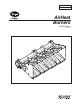
1 Introduction PRODUCT DESCRIPTION Eclipse AH-MA v2.10 Air Heat burners produce a uniform, odorless, and smokeless flame ideal for heating fresh air in make-up and process air heating applications.The AH-MA design provides stable operation over a wide range of velocities, inputs, and fuels. AH-MA v2.10 burners are line type burners constructed of cast iron or aluminum burner bodies and diverging stainless steel air wings.
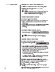
Safety NTRODUCTION I 2 In this section, you will find important notices about safe operation of a burner system. S AFETY Danger: The burners covered in this manual are designed to mix fuel with air and burn the resulting mixture. All fuel burn-ing devices are capable of producing fires and explosions when improperly applied, installed adjusted, controlled, or maintained. Do not bypass any safety feature. You can cause fires and explosions.
CAPABILITIES Adjustment, maintenance and troubleshooting of the mechanical and the electrical parts of this system should be done by qualified personnel with good mechanical aptitude and experience with combustion equipment. OPERATOR TRAINING The best safety precaution is an alert and competent operator. Thoroughly instruct new operators so they demonstrate an adequate understanding of the equipment and its operation. Regular retraining must be scheduled to maintain a high degree of proficiency.
System Design DESIGN 3 Design structure Designing a burner system is a straight-forward exercise of combining modules that add up to a reliable and safe system. The design process is divided into the following steps: 1. Burner design a. calculating the maximum input requirements b. choosing design heat input at high fire c. determining the length of burner needed d. calculating the minimum input requirements e. layout of the burner sections f. sizing and layout of the gas manifold g.
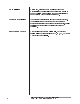
Step 1: Burner design Calculating the maximum input requirements To calculate the total burner maximum input required, solve: Max. Input (Btu/hr) = 1.3 x SCFM x ∆T (max) Caution: This is an approximation based on the gross heating value of the fuel. For more accurate heat balance calculations, refer to the Eclipse Combustion Engineering Guide (EFE-825). Choosing design heat input at high fire See Data Sheet No.
2) From the Operating Range chart in Data Sheet No. 160, the maximum heat input at 0.7"w.c. air pressure drop is 800,000 Btu/hr/ft. The flame length from the Flame Length chart in Data Sheet No. 160 is 30". Burner length, feet = 6,240,000 Btu/hr = 7.8 feet; round up to 8 feet. 800,000 Btu/hr/ft 3) Minimum: Btu/hr = 1.3 X 60,000 X 5 = 390,000 Btu/hr. 4) Minimum per foot = 390,000 Btu/hr = 48,750 Btu/hr/ft. 8 ft. 5) From the Operating Range chart in Data Sheet No. 160, the minimum input at 0.7 w.c.
Eclipse AH-MA Air Heat Burner v2, Design Guide 160, 8/1/05 Figure 3.1 9.6" 1.6" 5.9" 1.9" 11.8" 300mm x 300mm Cross 2.0" I.D. 10.6" 150mm Straight Section 5.9" 10.6" 9.6" 1.6" 5.9" 9.6" 2.2" 1.6" 300mm Straight Section with Back Inlet 1.5" I.D. 11.8" 10.
Eclipse AH-MA Air Heat Burner v2, Design Guide 160, 8/1/05 13 9.6" 1.6" 5.9" 11.8" 1.9" 10.6" 300mm x 300mm Cross 2.0" I.D. 150mm Straight Section 5.9" 10.6" Figure 3.1 (Continued) 9.6" 1.6" 5.9" 9.6" 2.0" 1.6" 300mm Straight Section with Back Inlet 2.0" I.D. 11.8" 10.
Eclipse AH-MA Air Heat Burner v2, Design Guide 160, 8/1/05 3.9" 2.6" 2" 1.3" 0.8" Plain End Plate Assembly 3.9" 8.7" 102257 10010970 10010972 10010974 10010975 10010976 10010977 10010978 10010979 10010980 101237 101238 101233 101234 101235 101236 102257-1 10010970-1 10010972-1 10010974-1 10010975-1 10010976-1 10010977-1 10010978-1 10010979-1 10010980-1 101237-1 101238-1 101233-1 101234-1 101235-1 101236-1 — — 1" NPT 1" BSP 1.5"NPT 1.
Sizing and layout of the gas manifold Choose the gas manifold size to evenly supply gas to each of the sections, using Table 3.3 and Figure 3.2. Table 3.3 Gas Pipe Sizing & Layout MAXIMUM GAS INPUT (MMBTU/HR.) 1.4 2.5 5.2 8.0 14.0 45.0 80.0 MANIFOLD PIPE SIZE (INCHES) 1-1/2 2 2-1/2 3 4 6 8 MAXIMUM GAS INPUT (MMBTU/HR.) 0.3 0.6 1.1 3.2 6.6 13.0 20.0 MAIN GAS PIPE SIZE (INCHES) 1/2 3/4 1 1-1/2 2 2-1/2 3 Note: Maximum inputs shown for natural gas only. For propane, multiply inputs by 1.
Profile plate sizing Profile plates are required to ensure sufficient air pressure drop across the burner. An example of profile plate layout is shown in Figure 3.4 on the next page. Caution: It is essential that even air flow is delivered to the burner to obtain optimum performance. To calculate the profile gap sizes, you will need to know the following: 1) SCFM = Total air flow around and through the burner in cubic feet per minute. 2) Design pressure drop across the burner.
Figure 3.3 Profile Gap Area vs. Air Pressure Gap Burner Air Inlet Temperature @ 70 F 110 Gp, Profile Gap Area Required (Sq. In. per 1000’s SCFM) 100 90 80 70 60 50 40 30 20 0.1 0.2 0.3 0.4 0.5 0.6 0.7 0.8 0.9 1.0 1.1 1.2 1.3 1.4 Combustion Air Pressure Drop ("w.c.) Table 3.4 Profile Gap Area Inlet Air Temperature Correction G @A P AIR TEMP. (°F) Correction Factor IR T EMP. = GP FROM FIG . 3.4 X CORRECTION F ACTOR 0 30 70 150 200 250 300 350 400 450 0.87 0.92 1.00 1.
Figure 3.5 Two-Stage Burner Profile Plates 6" Min. 3" Min. 6" Min. 2" 2" First Stage Burner Second Stage Burner Profile Plate Profile Plate 2" 2" X X X X 6" Min. Note: Make all profile gaps equal (shown as “X” above); profile plate width between the burners should be at least 3". Duct Wall Air Flow Air Flow Duct Wall Staged Burners Steel channel of the correct width can be used as the center profile plate. Install with the legs pointing toward the incoming air flow.
Note: To compensate for changes in actual air flow versus calculated, provide adjustable profile plates so that final settings can be made in the field. Figure 3.6 shows an example of an adjustable profile plate design. Figure 3.6 Adjustable Profile Plates AH-MA Burner Adjustable Profile Plate Elongated Screw Slots Fixed Profile Plate Duct Wall Side View Front View Figure 3.
Step 2: Control Methodology The simplest control method is fuel modulation at fixed air flow. If required turndown is greater than the burners capabilities, there are two options: 1. Air Modulation To lower the minimum input of the burner, the air flow can be decreased as long as the pressure drop across the burner does not go outside of the operating limits given in the Operating Ranges chart in Data Sheet No. 160.
2. Burner Fuel Staging To further increase the burner turndown, AH-MA v2.10 burners can be fuel staged. This can be done by installing two or more separate burners in a duct, each with its own gas control valve, or by dividing a single burner assembly into separate zoned sections. For example, to double the effective turndown, two burner sections may be staged as shown in Figure 3.8 on the previous page. If more heat is required, stage 2 is lit by simply supplying gas to it.
Step 4: Flame monitoring system A flame monitoring system consists of two main parts: a flame sensor a flame safeguard. Flame Sensor There are two types that you can use for an AH-MA v2.10 Air Heat burner: 90° U.V. scanner U.V. scanner flame rod. You can find information on U.V. scanners in: flame rod Instruction Manual No. 852; 90° U.V. scanner Instruction Manual No. 854; straight U.V. scanner Instruction Manual No. 855; solid state U.V.
Step 5: Gas Valve Train Selection Figures 3.9 and 3.10 illustrate gas valve trains for single and staged burner systems respectively. The typical main gas valve train for a staged burner has the same valve layout as a single burner except each burner has an individual solenoid valve to independently shut down each section. A common gas shut-off valve train can be used. Figure 3.
Figure 3.
Appendix CONVERSION FACTORS Metric to English. FROM TO MULTIPLY BY cubic meter (m ) cubic foot (ft ) 35.31 35.31 cubic meter/hour (m /h) cubic foot/hour (cfh) degrees Celsius (°C) degrees Fahrenheit (°F) (°C x 1.8) + 32 kilogram (kg) pound (lb) 2.205 kilowatt (kW) Btu/hr 3414 meter (m) foot (ft) 3.28 millibar (mbar) inches water column ("wc) 0.401 millibar (mbar) pounds/sq in (psi) 14.5 x 10 millimeter (mm) inch (in) 3.94 x 10 3 3 3 -3 -2 Metric to Metric.
Design Guide 160 8/1/05 Litho in U.SA.