Instruction Manual No. 826, 05/03 Bi-Flame Dual Burner Monitoring System Model 6500 Version 1.
COPYRIGHT Copyright 2003 by Eclipse Combustion. All rights reserved worldwide. This publication is protected by federal regulation and shall not be copied, distributed, transmitted, transcribed or translated into any human or computer language, in any form or by any means, to any third parties, without the express written consent of Eclipse Combustion.
About this manual AUDIENCE This manual has been written for the people who select and install the product and the technicians who work on it. They are expected to have previous experience with this kind of equipment. IMPORTANT NOTICES • Read this manual carefully. Make sure that you understand the structure and contents of this manual. • Obey all the safety instructions. • Do not deviate from any instructions or application limits in this manual without written consent from Eclipse Combustion.
Table of Contents 1 About this manual .................................................................... 3 Table of contents ....................................................................... 4 Introduction ................................................................................... 7 7 Product Description .......................................................................... 2 Specifications ..............................................................................
Function Summary .................................................................. 14 6 Introduction ........................................................................................... Standard Features................................................................................. Combustion Air Flow Check Terminal ............................................ Main Fuel Valve Proof-of-Closure Terminal .................................... Low Fire Start Terminal ...............................
7 Sensor Installation ................................................................... 27 Introduction ........................................................................................... Sensor Wiring ........................................................................................ Flame Rods ............................................................................................ Scanners ..............................................................................................
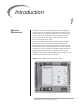
Introduction 1 PRODUCT DESCRIPTION The Eclipse Combustion Bi-Flame Burner Monitoring System controls the start-up sequence and monitors the flame of two individual gas, oil, or combination gas/oil burners connected to a common valve train. Its dynamic on-board testing checks for faulty relays, proof of valve closure, high and low fire switch interlocks, and shorted air switch.
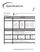
Specifications 2 INTRODUCTION This section gives a detailed overview of Bi-Flame specifications and dimensions. Specifications Parameter Supply Temperature Ranges Flame Failure Response TFI/Pilot Interrupt Purge Time Contact Ratings @ 120 VAC (maximum total connected load not to exceed 15 amps) Approvals Shipping Weight 8 Description •120 VAC (+10%, -15%), 50/60 Hz standard. Internal power consumption: 24VA Unit Model Nos. Temperature Range Bi-Flame 6500 -40˚ to +60˚C (-40˚ to +140˚F) 90˚ U.V.
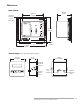
DIMENSIONS Main Chassis 140 mm (5-1/2") 183 mm (7-3/16") Mounting Holes (4) 5 mm (3/16") Dia. 237 mm (9-5/16") 229 mm (9") 21 mm (13/16") 270 mm (10-5/8") Remote Display (Shown with remote keypad and reset) 102 mm (4") Square 54 mm (2-1/8") 89 mm (3-1/2") Square Mounting Bracket & Screw (2) Mounting Bracket Slot (4) 15-pin Port Terminal Eclipse Bi-Flame v1.
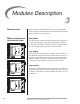
Modules Description 3 INTRODUCTION In this section, you will find descriptions of the various modules which comprise the Bi-Flame dual burner flame monitoring system, whether standard or optional items. MODULE DESCRIPTION Relay Module AND IDENTIFICATION The relay module contains the output relays which provide power for operating the ignition coil, pilot valve, main valve, combustion fan and alarm.
Sensor Module The sensor module is the flame sensing module of the Bi-Flame. It is mounted in the furthest right position of the mother board. On the front of the sensor module are two “Flame On” LED’s, which illuminate when a flame is detected at the corresponding burner. Directly below the “Flame ON” LED are “Flame Fail” LED’s, which energize to show the first burner to lose its signal. Sensor Module Location The sensor module incorporates test point connection jacks in the front of the unit.
DIP Switch Selection INTRODUCTION 4 This section details the location, selection and description of the Bi-Flame DIP switches, which allow for sequence and timing functions as well as system configuration. Caution: To avoid electric shock, shut off the power supply when installing any control device. Flame monitoring systems must be installed by a qualified, licensed technician.
DIP SWITCH SETTINGS ON/OFF 8 7 6 5 4 3 2 1 S6 50/60Hz — — Number of PAF S4 S2 8 7 6 5 4 3 2 1 P U R G E X4 120/8 60/4 30/2 15/1 TFI PILOT IMIT/IRPT RECYCLE DIP Switch Functions S2 ON — OFF X4 120 sec. Time Not 60 sec. Added 30 sec. 15 sec. S2 Modulation Purge Time, S4 - 8 = ON S2 8 7 6 5 4 The S2 DIP switches permit programming of timing and sequence functions of the Bi-Flame.
Function Summary INTRODUCTION 5 This section describes the function features of the Bi-Flame that can be found on the various terminal strips and the modules of the BiFlame. Combustion Air Flow Check Terminal The Bi-Flame checks that the combustion air flow switch is open before start-up, closed during operation and open again at burner shutdown, thus preventing operation with an air switch that is defective, maladjusted or jumpered.
Recycle Mode When selected, the Bi-Flame will restart the sequence after flame or air failure. The recycle mode allows the system to re-initiate the start-up sequence automatically, once the main burners have been operating for at least 20 seconds. If the pilot flame fails to light during recycling, the system will lock out and annunciate a pilot flame fail. If the recycle is successful and the main burners are operational for at least 20 seconds, the system is ready for another recycle.
Auxiliary Inputs This feature provides four auxiliary inputs which are monitored by the Bi-Flame as alarm interlocks. This means that when the input voltage is interrupted, the system locks out and will annunciate on the optional remote display unit. A voltage of 120 VAC must be present at the input for the Bi-Flame system to operate. If an auxiliary input loses its voltage for more than one second while the interlocks and limits input is powered, a lockout condition will occur.
History Log (continued) 4) Release the ENTER key and the most recent lockout message will display for seven seconds. 5) If you wish to see the next lockout message, press and release the ENTER key before the seven second time duration ends of the most recent lockout message display. This will prompt the next lockout message. If desired, continue this procedure until the maximum of ten lockout messages has been displayed (remember that the highest record number is the most recent lockout message).
Valve Leak Sensing Device (VLSD) Interface The Bi-Flame Valve Leak Sensing Device (VLSD or VDK) interface provides a 120 VAC output which triggers the start of the test period. An input is also provided which receives a 120 VAC signal from the VLSD. If the signal is received within the selected test period (40 or 110 seconds, see page 13), then the test has been successfully completed.
Remote Display Unit The remote display with keypad allows remote reset and activation of the history log option. It is panel mountable and features a backlit liquid crystal display in a 1/4 DIN housing. It connects to the BiFlame by a six or ten foot cable. The display incorporates the following features: 1) Provides status messages for the Bi-Flame sequence.
Air This LED illuminates when the air switch is closed and power is thereby applied to the air switch input. The Bi-Flame also checks this input for an air switch short (see “Combustion Air Flow Check Terminal” on page 14). Purge This LED illuminates whenever the combustion blower is energized, including the purge period and the main burner period of the sequence. It blinks on and off while the purge is in process and remains constant when the purge process is complete.
System Faults A system fault (illuminated by the fault LED on the logic cards) prevents gas ignition but does not lock out the system. System fault conditions are as follows: 1) If a flame is detected out of sequence, which may be caused by: a) a faulty scanner b) electrical interference on the sensor leads c) a flame exists in the burner due to a gas leak or other condition. 2) Air flow switch closed before start-up.
System Installation INTRODUCTION 6 In this section, the necessary procedures are detailed to integrate a Bi-Flame into a burner system; Figure 6.1 (page 25) illustrates the various terminal strips mentioned. Note: Shut off the power supply before any module is removed or replaced from the unit, including the remote display. Caution: Installation and maintenance must conform with the National Electrical Code and all other national and local codes and authorities having jurisdiction.
IGNITION WIRING Route ignition wiring a sufficient distance from all sensors and other low voltage wiring to avoid electrical interference, which may cause erratic operation of the Bi-Flame system. Caution: Do not connect multiple ignition coils in excess of output relay contact rating COMMUNICATION WIRING Route communication wiring, using shielded cable, a sufficient distance from ignition and other high voltage wiring to avoid electrical interference.
REMOTE RESET This feature permits remote mounting of a switch to reset the BiFlame. To use this feature, a normally closed remote reset switch must be wired between terminals 1 and 4 on terminal strip J7. When it is depressed or actuated, the connection between the terminals is momentarily interrupted and resets the Bi-Flame. This is a low voltage signal circuit that must be routed separately from other control voltage wiring.
Figure 6.1 Terminal Strips Identification & Location Main Chassis J4 J7 J1 J2 J6 J3 Remote Display Connection J5 Eclipse Bi-Flame v1.
Figure 6.2 Wiring Diagram & Connections–Main Chassis On/Off 15 A. Fuse 120 VAC J1 Terminals Interlocks & Limits Air Flow 1 High Fire Aux. Input #21 Aux. Input #31 Aux.
Sensor Installation INTRODUCTION 7 This section describes the proper wiring, installation and sighting considerations for all sensors that can be used with a Bi-Flame. Warning Incorrect sensor installation may cause the sensor to generate a false flame signal, causing unburned fuel to collect in the combustion chamber. The result can be explosions, injuries and property damage. Be certain that the flame sensor detects only pilot and main flames, not glowing refractory, burner or ignition parts.
FLAME RODS Flame rods should be used only on gas burners. They accumulate soot on oil burners, causing nuisance shutdowns and unsafe operating conditions. See the burner manufacturer’s literature for flame rod mounting location. When installing flame rods, please consider the following: 1) Keep the flame rod as short as possible and at least 13 mm (1/2") away from any refractory.
SCANNER SIGHTING CONDITIONS MAIN BURNER Scanner Sight Line 1/3 of Flame Length SCANNER U.V. Scanner Sighting Aim scanners at the third of the flame closest to the burner nozzle, as shown at left. This is especially true for oil flames which typically have less UV radiation in the outer flame.The scanner should view the intersection of the pilot and main flames.When sighting scanners, please consider the following: 1) Sight the scanner away from the ignition spark.
Test Procedures 8 INTRODUCTION This section describes the test procedures that must be performed after installation to insure that the Bi-Flame is operating properly; these procedures are mandatory. FLAME SIGNAL Insert the positive probe of a 0-15 VDC, one megohm/volt meter into the test point on the front cover, as shown in the photo at left. Connect the negative probe to ground. A good flame signal strength will read between 6 and 11 VDC; anything below 4 VDC is inadequate.
PILOT FLAME FAILURE TEST 1) Manually shut off the fuel supply to one individual pilot and main burner, or all burners if the system has a single fuel supply. 2) Place system in pilot test mode (please refer to page 15). 3) Start the system normally. The controller should lock out*; if it doesn’t, then the controller is detecting a false flame signal (see Section 7). Find the problem and correct it before resuming normal operation. 4) Repeat steps 1 through 4 until all burners have been tested.
Maintenance and Troubleshooting INTRODUCTION 9 This section is divided into two parts: • The first part describes the maintenance procedures. • The second part helps you to identify problems that may occur, and gives advice on how to solve these problems. MAINTENANCE Preventative maintenance is the key to a reliable, safe and efficient system. The core of any preventive maintenance program is a list of periodic tasks. In the paragraphs that follow are suggestions for a monthly list and a yearly list.
Yearly Checklist 1. Test (leak test) safety shut-off valves for tightness of closure. 2. Test pressure switch settings by checking switch movements against pressure setting and comparing with actual impulse pressure. 3. Visually check ignition cable and connectors. 4. Make sure that the following components are not damaged or distorted: • the burner nozzle • the spark plugs • the flame sensors • the flame tube or combustion block of the burner Eclipse Bi-Flame v1.
TROUBLESHOOTING PROBLEM POSSIBLE CAUSE Cannot initiate start sequence SOLUTION • Main valve is not closed. Check proof-of-valve-closure switch. • Air pressure switch has not made contact. Check air pressure switch adjustment. Check air filter. Check blower rotation. Check outlet pressure from blower. • High gas pressure switch has tripped. Check incoming gas pressure; adjust gas pressure if necessary. Check pressure switch setting and operation. • Low gas pressure switch has tripped.
Remote Display Messages INTRODUCTION 10 This section covers how the optional remote display is used with the Bi-Flame. The remote display provides LCD messages which monitor the status of the Bi-Flame’s functions as well as any lockout conditions. This section is divided into two parts or tables: • The first table describes the start-up and shutdown monitoring sequences of the Bi-Flame and how the progress (or halt) of the sequence can be monitored by the messages on the remote display.
Table 10.1 Bi-Flame Operating Sequence POWER ON Was internal safe start check successful? NORMAL MESSAGE YES VERSION VX.X CHECKSUM = XXXX NO Various lockout messages EXTERNAL INTERLOCK CHECKS Is flame signal present? ERROR MESSAGE #1 YES UNSAFE FLAME ON If signal is eliminated within 30 seconds, sequence continues. If not, then . . .
Table 10.1 Bi-Flame Operating Sequence (continued) BURNER START-UP Is voltage present at air flow switch within ten seconds? NORMAL MESSAGE AIR PROVEN YES NO ERROR MESSAGE AIR NOT PROVEN LKOUT XXXX:XX:XX NORMAL MESSAGE WAIT FOR HI. FIRE SWITCH XX:XX Modulator sent to high fire. Is voltage present at high fire input? YES NO NORMAL MESSAGE PURGE AT HIGH FIRE XX Countdown of “XX” seconds as set by DIP switch. ERROR MESSAGE HIGH FIRE FAIL LKOUT XXXX:XX:XX NORMAL MESSAGE WAIT FOR LO.
Table 10.1 Bi-Flame Operating Sequence (continued) BURNER START-UP (continued) Is flame signal present ? YES NO ERROR MESSAGE MAIN # (OX) FAILED X = burner number. NORMAL MESSAGE MAIN FLAME ON NORMAL MESSAGE MAIN FLAME ON PILOT OFF IF Interrupted Pilot is selected Pilot will shut off 10 seconds after main flame is energized. NORMAL MESSAGE AUTOMATIC MODULATION Modulator sent to automatic 20 seconds after main valve is energized. NORMAL MESSAGE FLAME #(OX) XX.
Table 10.1 Bi-Flame Operating Sequence (continued) BURNER SHUTDOWN Shutdown is started by opening the operating interlock circuit. Is voltage present at interlocks? YES Continued operation. NORMAL MESSAGE NO POST PURGE XX Fuel valves de-energized; fan energized for 15 seconds. Is proof of closure circuit closed? YES ERROR MESSAGE NO MAIN VALVE FAIL LKOUT XXXX:XX:XX Fan and alarm energized.
Table 10.2 Remote Display Diagnostic Messages (Listed Alphabetically) MESSAGE 40 TYPE EXPLANATION AIR FAILURE LKOUT XXXX:XX:XX Lockout Combustion air flow limit switch (strip J1, terminal 2) opened for more than two seconds once initially proven. AIR FAILURE RECYCLING Status Combustion air flow limit switch (strip J1, terminal 2) opened; control will recycle once if “recycle” DIP switch has been selected.
Table 10.2 Remote Display Diagnostic Messages (continued) MESSAGE TYPE EXPLANATION MAIN # ( ) FAILED Lockout Main flame was not established during the main burner trial for ignition. MAIN FLAME ON Lockout Main valve has been energized and main flame proven during trial for ignition. MAIN FLAME ON PILOT OFF Status Pilot valve (strip J2, terminal 5) is de-energized and main flame is on.
Table 10.2 Remote Display Diagnostic Messages (continued) MESSAGE 42 TYPE EXPLANATION UNSAFE FLAME ON Hold Flame signal—actual, induced, or faulty scanner—is detected before start-up or after shutdown. The fan is energized. If the cause is corrected within 30 seconds, as in afterburn, the control will turn off the fan and continue the sequence.
Appendix CONVERSION FACTORS Metric to English. FROM TO MULTIPLY cubic meter (m3) cubic meter/hour (m3/h) cubic foot (ft3) cubic foot/hour (cfh) 35.31 35.31 degrees Celsius (°C) degrees Fahrenheit (°F) (°C x 1.8) + 32 kilogram (kg) pound (lb) 2.205 kilowatt (kW) meter (m) Btu/hr foot (ft) 3414 3.28 millibar (mbar) inches water column ("wc) 0.401 millibar (mbar) pounds/sq in (psi) 14.5 x 10⁻³ millimeter (mm) inch (in) 3.94 x 10⁻² BY Metric to Metric.
ILLUSTRATED PARTS LIST Pos. No. Qty. 1 1 Mother Board (6500M) 20315 2 1 Relay module circuit board 22494 3 1 Logic module circuit board 22495 4 1 Power module circuit board 22496 5 1 Sensor circuit board 20314 6 1 183 cm (6ft) cable for remote display 15426 6 1 305 cm (10ft) cable for remote display 7 1 Remote display with keypad Eclipse Part Number Description 15426-1 15422 Downtimes due to a failure can be kept to a minimum by stocking recommended spares.
Eclipse Bi-Flame v1.
826 Instruction Manual 05/03