
User Manual


5
3. INSTALLATION and CONNECTION
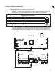
Installing a MPAGE4 unit consists of the following steps:
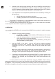
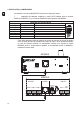
1. Installation of wiring using a standard CAT5 cable between the BASE connector of
the MPAGE4 (7) and the PAGER connector on the rear panel of the MIMO54.
Wiring of RJ-45 connector
Pin 1 to Pin 1 White/orange MIC+
Pin 2 to Pin 2 Orange MIC-
Pin 3 to Pin 3 White/green GND
Pin 4 to Pin 4 Blue VCC (+10V)
Pin 5 to Pin 5 White/blue ZONE 1
Pin 6 to Pin 6 Green ZONE 2
Pin 7 to Pin 7 White/brown ZONE 3
Pin 8 to Pin 8 Brown ZONE 4
The cable transmits the zone selection control signals as well as the audio signal of
the goose-neck microphone and the signal for the carillon melody, if activated. The
phantom
power required by the MPAGE4 unit is also supplied by the MIMO54 using
the same cable.
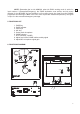
LINE L
MIC
LINE R
010
VOL
ZONE 1
ZONE 2ZONE 3
EVACPRIO
INPUT 5OUTPUT PAGER
PAGER
CHIME
MIMO54
MPAGE4