USER MANUAL MANUAL DE INSTRUCCIONES NOTICE D'UTILISATION BEDIENUNGSANLEITUNG MPAGE4 4 ZONE PAGING STATION
INSTRUCTION MANUAL 1. IMPORTANT NOTE 1.1. Precautions 04 04 2. INTRODUCTION 04 3. INSTALLATION and CONNECTION 05 4. OPERATION 06 5. FUNCTIONS LIST 07 6. FUNCTIONS DIAGRAM 07 7. TECHNICAL CHARACTERISTICS 23 All numbers subject to variation due to production tolerances. ECLER SA reserves the right to make changes or improvements in manufacturing or design which may affect specifications.
1. IMPORTANT NOTE We would like to thank you for choosing the MPAGE4 paging station. For the maximum effectiveness of the paging station, it is VERY IMPORTANT that you read this User's Guide carefully and follow the recommendations contained herein. In order to guarantee the optimum operation of this unit, we strongly recommend that its maintenance be carried out by our Authorised Technical Services. 1.1.
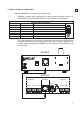
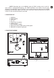
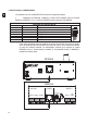
3. INSTALLATION and CONNECTION Installing a MPAGE4 unit consists of the following steps: 1. Installation of wiring using a standard CAT5 cable between the BASE connector of the MPAGE4 (7) and the PAGER connector on the rear panel of the MIMO54.
2. Activation of the carillon melody (optional). With the two CHIME (6) micro-switches on the rear panel of the MPAGE4 it is possible to: deselect the carillon melody (both set to OFF) or select one of three carillon melodies combining the ON and OFF positions (ON-OFF, OFF-ON and ON-ON). ON position = micro switch down. 3.
NOTE: Remember that on the MIMO54, when the EVAC working mode is active for input number 5 (Evacuation/Emergency), the ZONE destination zone selector and the zones selected for the MPAGE4 Unit are disabled. In this working mode, the signal from the PAGING programme and warnings in ALL of the unit's zone outputs are muted and replaced by the signal in input 5 or the evacuation/emergency message. 5. FUNCTIONS LIST 1. PAGE key 2. PAGE indicator 3. Zone keys 4. ALL key 5. Goose-neck microphone 6.
MANUAL DE INSTRUCCIONES 1. NOTA IMPORTANTE 1.1. Precauciones 09 09 2. INTRODUCCIÓN 09 3. INSTALACIÓN y CONEXIONADO 10 4. FUNCIONAMIENTO 11 5. LISTA DE FUNCIONES 12 6. DIAGRAMA DE FUNCIONES 12 7. CARACTERÍSTICAS TÉCNICAS 23 Todos los datos están sujetos a variación debida a tolerancias de producción. ECLER S.A. se reserva el derecho de realizar cambios o mejoras en la fabricación o diseño que pudieran afectar las especificaciones.
1. NOTA IMPORTANTE Agradecemos su confianza por haber elegido nuestra estación de avisos MPAGE4. Para conseguir su máxima operatividad y rendimiento es MUY IMPORTANTE, antes de su conexión, leer detenidamente y tener muy presentes las consideraciones que en este manual se especifican. Para garantizar el óptimo funcionamiento de este aparato recomendamos que su mantenimiento sea llevado a cabo por nuestros Servicios Técnicos autorizados. 1.1.
3. INSTALACIÓN y CONEXIONADO La instalación de una unidad MPAGE4 consta de los siguientes pasos: 1. Instalación del cableado, mediante un cable CAT5 estándar entre el conector BASE de la MPAGE4 (7) y el conector PAGER del panel posterior del MIMO54.
2. Activación de la melodía de carillón (opcional). Mediante los 2 microinterruptores CHIME (6) del panel posterior de la MPAGE4 es posible: o no activar la melodía de carillón (ambos en OFF), o bien seleccionar una melodía de carillón de entre tres posibles, combinando las posiciones ON y OFF de ambos (ON-OFF, OFF-ON y ONON). Posición ON = microinterruptor abajo. 3.
NOTA: Recuerde que en el MIMO54, cuando se encuentra activo el modo de trabajo EVAC para la entrada número 5 (Evacuación / Emergencia), el selector de zonas de destino ZONE, así como las zonas seleccionadas en una unidad MPAGE4, quedan inhabilitados, dado que en dicho modo siempre se enmudece la señal de programa y avisos de PAGING presente en TODAS las salidas de zona de la unidad, reemplazándola por la señal existente en la entrada nº 5, o mensaje de evacuación / emergencia. 5. LISTA DE FUNCIONES 1.
NOTICE D’UTILISATION 1. NOTE IMPORTANTE 1.1. Précautions 14 14 2. INTRODUCTION 14 3. INSTALLATION et CONNEXIONS 15 4. FONCTIONNEMENT 16 5. LISTE DE FONCTIONS 17 6. SCHÉMA DE FONCTIONS 17 7. CARACTÉRISTIQUES TECHNIQUES 23 Toutes les valeurs mentionnées dans ce document sont susceptibles d’être modifiées en raison des tolérances de production.
1. NOTE IMPORTANTE Nous vous remercions de la confiance que vous nous avez témoignée en choisissant notre console d'annonces MPAGE4. Pour en tirer le meilleur rendement et un fonctionnement maximal, il est TRÈS IMPORTANT de lire attentivement et de respecter les indications données de ce manuel avant toute connexion. Pour obtenir le meilleur rendement de cet appareil, il est important que l'entretien soit réalisé par notre Service Technique Ecler. 1.1. Précautions Eviter tout contact avec l'eau.
3. INSTALLATION et CONNEXION L'installation d'une unité MPAGE4 doit suivre les étapes suivantes : 1. Installation du câblage par câble CAT5 standard entre le connecteur BASE de la console MPAGE4 (7) et le connecteur PAGER du panneau arrière de l'unité MIMO54.
2. Activation de la mélodie de carillon (en option). Les 2 micro-interrupteurs CHIME (6) du panneau arrière de la console MPAGE4 permettent : d'activer ou non la mélodie de carillon (les deux sont sur OFF), ou de sélectionner une mélodie de carillon parmi trois choix, en modulant les positions (ON-OFF, OFF-ON et ON-ON). Position ON = micro-interrupteur en bas. 3.
NOTE : N'oubliez pas que sur l'unité MIMO54, lorsque le mode de travail EVAC est activé pour l'entrée numéro 5 (Évacuation / Urgences), le sélecteur de zones de destination ZONE et les zones sélectionnées sur une unité MPAGE4 sont déshabilités, car dans ce mode le signal de programme et d'annonces PAGING présent dans TOUTES les sorties de zone de l'unité devient muet et est remplacé par le signal existant dans l'entrée n° 5 ou par un message d'évacuation ou d'urgence. 5. LISTE DE FONCTIONS 1.
BEDIENUNGSANLEITUNG 1. WICHTIGER HINWEIS 1.1. Vorsichtsmaßnahmen 19 19 2. EINLEITUNG 19 3. INSTALLATION und ANSCHLUSS 20 4. BETRIEB 21 5. LISTE DER FUNKTIONEN 22 6. FUNKTIONSDIAGRAMM 22 7. TECHNISCHE DATEN 23 Alle angegebenen Werte unterliegen gewissen Schwankungen infolge Produktionstoleranzen. ECLER S.A. behält sich das Recht zu Änderungen oder Weiterentwicklungen in Produktion oder Design vor, die Abweichungen der technischen Daten zur Folge haben können.
1. WICHTIGER HINWEIS Wir bedanken uns für das Vertrauen, das Sie mit der Wahl unserer Sprechstelle MPAGE4 in uns gesetzt haben. Um eine optimale Handhabung und die maximale Leistung zu erhalten, ist es SEHR WICHTIG, vor dem Anschluss des Geräts die in dieser Anleitung enthaltenen Hinweise aufmerksam durchzulesen und zu berücksichtigen. Damit ein optimaler Betrieb gewährleistet ist, sollten eventuelle Reparaturen nur von unserer technischen Service Abteilung durchgeführt werden. 1.1.
3. INSTALLATION und ANSCHLUSS Für die Installation einer MPAGE4 sind folgende Schritte notwendig: 1. Installation der Kabelverbindung mittels eines CAT5-Standardkabels zwischen dem Anschluss BASE der MPAGE4 (7) und dem Anschluss PAGER am Anschlussfeld auf der Rückseite der MIMO54.
2. Aktivierung der Glockenspielmelodie (Option). Die beiden Mikroschalter CHIME (6) auf der Rückseite der MPAGE4 bieten folgende Möglichkeiten: Deaktivierung der Glockenspielmelodie (beide Schalter auf OFF) oder Auswahl einer Glockenspielmelodie aus den drei möglichen Melodien durch unterschiedliche Stellungskombinationen ON und OFF der beiden Schalter (ON-OFF, OFF-ON und ON-ON). Stellung ON = Mikroschalter unten. 3.
HINWEIS: Bitte beachten: Wenn an der MIMO54 die Betriebsart EVAC für den Eingang Nr. 5 (Evakuierung / Notfall) aktiv ist, werden der Zielzonenwählschalter ZONE und die an der MPAGE4 ausgewählten Zonen deaktiviert, weil in dieser Betriebsart das Programmsignal und die PAGING-Durchsagen an ALLEN Zonenausgängen der Konsole stummgeschaltet und durch ein am Eingang Nr. 5 vorhandenes Signal bzw. eine Evakuierungs-/Notfalldurchsage ersetzt werden. 5. LISTE DER FUNKTIONEN 1. Taste PAGE 2. Anzeige PAGE 3.
7. TECHNICAL CHARACTERISTICS 7. CARACTÉRISTIQUES TECHNIQUES 7. CARACTERÍSTICAS TÉCNICAS 7. TECHNISCHE DATEN Microphone type Non removable gooseneck condenser microphone Polar pattern Unidirectional Microphone frequency response 50Hz – 18KHz (-10dB) Output level 0dBV @ 104dB SPL ±7dB (internal adj.
ECLER Laboratorio de electro-acústica S.A. Motors 166-168, 08038 Barcelona, Spain INTERNET http://www.ecler.com e-mail: info@ecler.es 50.0230.01.