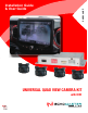
EMUBCAMKIT Installation Guide & User Guide UNIVERSAL QUAD VIEW CAMERA KIT with DVR
Installation Guide EMUBCAMKIT Universal Quad View Camera Kit Important Please read and follow the instructions carefully. To emphasize special information, the symbol and the words Warning, Caution and Note have special meanings. Pay special attention to messages highlighted by these signal words. These instructions are designed as a guide to help make the installation of this product successful. Always use caution and ask for assistance if you are not sure how to proceed.
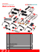
Installation Guide EMUBCAMKIT Universal Quad View Camera Kit What’s in the box 1 2 3 4 5 10 7 8 6 9 12 12 14 11 13 Image 1 2 3 4 5 6 7 8 9 10 11 12 13 14 Description IR/Display Mode Harness Camera Extension Cable Camera Input Adapter Interface Power/Trigger Harness IR Remote Control Power Switch AVS-21 Harness Video Output Harness AVS-21 Video Switcher Camera/Video Interface AHD Cameras USB Cable Mount screw RCA cable Qty 1 4 4 1 1 1 1 1 1 1 4 1 4 1 3 tel - 1-800-477-2267 email - support@echo
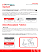
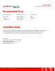
Installation Guide EMUBCAMKIT Universal Quad View Camera Kit Recommended Tools Plastic Trim Tool Socket Set Ratchet Screwdrivers Diagonal Cutters Wire Crimpers Electrical Tape Wire Feeder Utility Knife Drill Brill Bits Installation Notes Read this installation guide thoroughly before disassembling vehicle or making wire connections. Installation of this product requires technical skill, experience, and specialized tools.
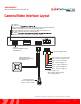
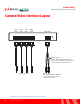
Installation Guide EMUBCAMKIT Universal Quad View Camera Kit Camera/Video Interface Layout DIP Switches DIP switches 1-4 When in the OFF(DOWN) postion, the camera image will be normal (Non-Mirrored). Non-Mirrored should be used for any forward facing cameras. When in the ON (UP) postion, the camera image will reversed (Mirrored). Mirrored should be used for any rear facing cameras. DIP switch 5 AHD 25fps, NTSC, PAL. See page 15 for setting video output.
Pink - Camera Trigger (+) Pink - Camera 4 Trigger4(+) Trigger (+) Orange -Orange Camera- Camera 3 Trigger3(+) Installation Guide Green - Camera Trigger (+) Green - Camera 2 Trigger2(+) White - Camera Trigger (+) White - Camera 1 Trigger1(+) EMUBCAMKIT Universal Quad View Camera Kit When +12V is applied, When +12V is applied, displaysdisplays corresponding corresponding camera. camera. Camera/Video Interface Layout signal ReceivesReceives signal from thefrom the remote control.
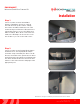
Installation Guide EMUBCAMKIT Universal Quad View Camera Kit Installation Step 1 Select a location for the Camera/Video Interface. Behind the glove box or below the radio are both good locations. Ideally, the location should be within two feet of the monitor being used. Run the USB extension to a desired position to access the USB port for DVR recordings. Once all the connections are made, two sided tape can be used to secure the module or you can secure with screws.
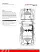
Installation Guide EMUBCAMKIT Universal Quad View Camera Kit Installation (continued) Step 3 Positioning The Cameras: The cameras can be placed anywhere; wheel wells, frame, bumpers, axle. Facing in any direction; forward, rearward, sideways. FIG A Note: The cameras come with the mounting bracket at the top of camera (FIG A).
Installation Guide EMUBCAMKIT Universal Quad View Camera Kit Step 4 Routing The Camera Cables: Attach a Camera Extension Cable to each camera and route the camera cables to the video interface inside the vehicle. Follow the factory wiring harnesses whenever possible. Secure with zip ties. Most vehicles will have rubber grommets located in the floor that will allow the cables to be safely passed from the outside to the inside.
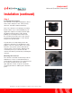
Installation Guide EMUBCAMKIT Universal Quad View Camera Kit Installation (continued) Step 5 For each camera; plug in a Camera Input Adapter (1) into the video interfaces camera input. Align the arrows on the Camera Input Adapter and Camera Extension Cable (2) and connect the cables. Front Cam1-in Rear Cam2-in Left Cam3-in Right Cam4-in Video-out 1 2 Step 6 DIP switches 1-2-3-4 on the side of the module correspond to Camera Inputs 1-2-3-4.
Installation Guide EMUBCAMKIT Universal Quad View Camera Kit Wiring Guide There are several different ways to connect the video interface to your monitor source. We have included several Wiring Diagrams. NOTE: If you are connecting to an after-market radio, you may need to remove the radio or refer to the radios owners manual to determine how to wire the video interface. All installations require the power/ground connections in Step 1 below.
Installation Guide EMUBCAMKIT Universal Quad View Camera Kit Wiring Guide 1 Follow these instructions if you are connecting to: • Stand-alone monitor • After-market radio with Rear camera input, No rear camera installed and On-screen option to turn-on camera • After-market Radio with two or more camera inputs (with one of them not being used) and On-screen option to turn-on camera Step 1 Plug the Video Output Harness into the video interface.
Installation Guide EMUBCAMKIT Universal Quad View Camera Kit Wiring Guide 2 Follow these instructions if you are connecting to: • After-market radio with Rear camera input, rear camera installed and On-screen option to turn-on camera • Factory radio with a camera interface that can turn on the camera input manually. This type of installation requires using the Power Switch and the PAC AVS-21 to switch the video signal between the rear camera and the video interface.
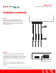
Installation Guide EMUBCAMKIT Universal Quad View Camera Kit Wiring Guide 2 (cont.) Step 4 Plug the Video Output Harness into the video interface. Step 5 Connect either the CVBS or AHD RCA to the AV2 IN on the AVS-21. If the radio does not specifically say Analog High Definition, use CVBS. Insulate the red and blue wires when not using. 4 Step 6 Unplug the rear camera RCA from the radios camera input and plug it into AV1 IN on the AVS-21.
Installation Guide Used to switch (trigger) the monitor to camera source if manual camera activation is not available on the monitor source. EMUBCAMKIT Universal Quad View Camera Kit One of outputs (AHD or CVBS) will connect to the AVS21 or directly to the monitor source. The video interface can output four different video signals: AHD 30 fps, AHD 25 fps, CVBS NTSC and CVBS PAL. The default setting on initial power up is CVBS NTSC.
User Guide EMUBCAMKIT Universal Quad View Camera Kit User Guide IR Remote Control IR Receiver When viewing the video interface, use the IR Remote control to switch between display modes and access Settings. MENU Access the settings menu (Page: 18) Navigation Arrows Up / Down / Left / Right Camera Select Press to select camera in full screen view.
User Guide EMUBCAMKIT Universal Quad View Camera Kit Display Modes Along with full screen modes for each camera, the video interface has different display modes that allow viewing multiple cameras at the same time. Change display modes via the IR Remote Control or the Display Mode Button. The last display mode viewed will be kept in memory when the vehicle is turned off.
User Guide EMUBCAMKIT Universal Quad View Camera Kit Settings Menu Pressing the MENU button on the IR Remote Control will bring up the Settings Menu. Use the arrows to navigate the settings icons. Press OK to select highlighted icon. In the setting sub-menu, use the arrows to highlight or change desired setting and the then press OK to save and exit. Loop Time Sets recording time for saved video files.
User Guide EMUBCAMKIT Universal Quad View Camera Kit Input Type Sets input video type/resolution. 720p 25fps / 720p 30fps / CVBS PAL / CVBS NTSC 720p 30fps recommended Info Udisk Info Clock Allows setting the time and date. This is important for time-stamping the recorded video files. Udisk Output Type (Normal Video) = Recorded Percentage used on storage device. (SOS Video) = Recorded Percentage used on storage device. Light freq 50Hz / 60Hz Format Formats the Micro SD Card.
ecording. e Receives signal from the wireless remote control. Switches between cameras and display modes. correspond to Cameras 1-4 the OFF(DOWN) postion, the camera image will be normal (Non-Mirrored). rored should be used for any forward facing cameras. the ON (UP) postion, the camera image will reversed (Mirrored). should be used for any rear facing cameras.