
Installation Manual

Milestone AV Technologies and its a liated corporations and subsidiaries (collectively,
“Milestone”), intend to make this manual accurate and complete. However, Milestone
makes no claim that the information contained herein covers all details, conditions,
or variations. Nor does it provide for every possible contingency in connection with
the installation or use of this product. The information contained in this document
is subject to change without notice or obligation of any kind. Milestone makes no
representation of warranty, expressed or implied, regarding the information contained
herein. Milestone assumes no responsibility for accuracy, completeness or su ciency
of the information contained in this document.
©2015 Milestone AV Technologies. All rights reserved. ECHOGEAR is a Milestone
brand.
ECHOGEAR and the ECHOGEAR logo are trademarks of Milestone.
Made in China.
Milestone Global Headquarters • 6436 City West Parkway • Eden Prairie, MN 55344 USA
16 in.
(406 mm)
2-1 2-2 2-3 2-4
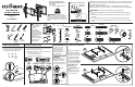
Step 3
Adjustments
6901-002429 02
01
01
08
09
05
05
03
01
01
02
01
To adjust TV level, loosen the 2 bolts on
the rear of the arm plate, adjust level,
and retighten to secure.
Step 5
Step 4
05
05
Hang TV with
brackets
05
onto the
upper
arm
extensions
02
and
03
.
Note: TV brackets
05
must
span the
faceplate of the arm and be centered.
Secure TV with brackets
05
to the
lower arm
extensions
02
and
03
with the bracket clips
21
and screws
07
.
Ensure that the
bracket clips
21
and screws
07
are firmly attached and that the
TV with
brackets
05
cannot slide side-to-side
.
02
02
03
04
04
03
Install arm extensions
02
and
03
and end caps
04
.
07
07
10
07
07
06
06
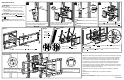
Step 2 Wood Stud
N
o
t
e
O
r
i
e
n
t
a
t
i
o
n
UP
3 in. (75 mm)
7/32 in.
(5.5 mm)
03
02
To adjust TV tilt, loosen the handle on
the arm plate, tilt TV to desired angle,
and retighten handle to secure.
CAUTION: Avoid potential personal injuries and
property damage!
● Drywall covering the wall must not exceed
5/8 in. (16 mm)
● Minimum wood stud size: common 2 x 4 in.
(51 x 102 mm) nominal 1½ x 3½ in. (38 x 89 mm)
CAUTION: Avoid potential personal injury or
property damage! All lag bolts
08
MUST BE firmly
tightened to prevent unwanted movement of the wall
plate
01
.
CAUTION: Ensure the wall plate is securely
fastened to the wall before continuing on to the next
step.
Locate your studs. Verify and mark the center of
the studs by fi nding the stud edges using an awl,
a thin nail, or an edge-to-edge stud fi nder.
Install wall plate
01
using lag bolts
08
and
washers
09
. Tighten the lag bolts
08
only until
they are pulled firmly against the wall plate
01
.
Position the wall plate
01
at your desired height
and line up the holes with your stud center line.
Level the wall plate and mark the holes.
Drill pilot holes using a 7/32 in. (5.5 mm) diameter
drill bit.
IMPORTANT: Be sure to drill into the center of the
stud.
IMPORTANT: Pilot holes must be drilled to a depth
of 3 in. (75 mm).
02
03
07
07
05
21