
Use and Care Manual
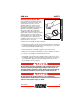
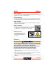
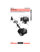
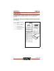
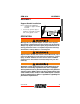
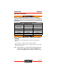
Table Of Contents
- SRM-2620 GRASS TRIMMER / BRUSH CUTTER
- Table of Contents
- Introduction 4
- Description 15
- Contents 18
- Product Registration 44
- Introduction
- The Operator’s Manual
- The Safety Manual
- Servicing Information
- Safety
- (Exhaust & Evaporative)
- Description
- 1. POWER HEAD - Includes the Engine, Clutch, Fuel System, Ignition System and Recoil Starter.
- 2. THROTTLE HANDLE - FOR RIGHT HAND - Contains Stop Switch, Throttle Lockout, and Throttle Trigger.
- 3. THROTTLE TRIGGER LOCKOUT - This lever must be held during starting. Operation of the throttle trigger is prevented unless throttle trigger lockout lever is engaged.
- 4. STOP SWITCH - “SLIDE SWITCH” mounted on top of the Throttle Handle. Move switch FORWARD to RUN, BACK to STOP.
- 5. SUPPORT HANDLE - FOR LEFT HAND - The support handle is factory assembled to the Drive Shaft assembly but must be re- positioned for proper cutting attitude and operator comfort.
- 6. DRIVE SHAFT ASSEMBLY - Includes the Throttle Handle, Gear Housing assembly, Support Handle, Drive Shaft and Safety Decal.
- 7. NYLON CUTTER HEAD - Contains replaceable nylon trimming line that advances when the trimmer head is tapped against the ground while the head is turning at normal operating speed.
- 8. CUT-OFF KNIFE - Automatically trims line to the correct length: 13 cm (5 inches) after head is tapped on the ground. If trimmer is operated without a cut-off knife, the line will become too long, the engine will overheat, and engine damage may occur.
- 9. DEBRIS SHIELD with CUT-OFF KNIFE - Required when unit is equipped with nylon line head. Do not operate unit without shield.
- 10. THROTTLE TRIGGER - Spring loaded to return to idle when released. During acceleration, press trigger gradually for best operating technique
- 11. SPARK PLUG - Provides spark to ignite fuel mixture.
- 12. ARM REST - Provides arm rest during operation and protects arm from the hot engine.
- 13. RECOIL STARTER HANDLE - Pull handle slowly until starter engages, then quickly and firmly. When engine starts, return handle slowly. DO NOT let handle snap back or damage to unit will occur.
- 14. SPARK ARRESTOR MUFFLER OR SPARK ARRESTOR MUFFLER WITH CATALYST -The muffler or catalytic muffler controls exhaust noise and emission. The spark arrestor screen prevents hot, glowing particles of carbon from leaving the muffler. Keep exhaust area ...
- 15. FUEL TANK - Contains fuel and fuel filter.
- 16. FUEL TANK CAP - Covers and seals fuel tank opening.
- 17. CHOKE - The choke control is located at the rear of the air cleaner housing. Move choke lever to COLD START () to close choke for cold start. Move choke lever to “RUN” () position to open choke.
- 18. AIR CLEANER - Contains replaceable filter element.
- 19. PURGE BULB - Pumping purge bulb before starting engine draws fresh fuel from the fuel tank, purging air from the carburetor. Pump purge bulb until fuel is visible and flows freely in the clear fuel tank return line. Pump purge bulb an additional ...
- Contents
- Assembly
- Operation
- Operation With Blades
- Support Handle, w/ or w/ o Barrier Bar
- U-Handle or Support Handle w/Barrier Bar
- U-Handle or Support Handle w/Barrier Bar
- Shield w/cutoff knife
- Shield w/cutoff knife
- Shield w/o cutoff knife
- Harness
- Harness
- Harness
- Upper Plate & Flat Washer
- Upper Plate & Glide Cup
- Upper/Lower Blade Plates
- Hex Nut
- Hex Nut
- Hex Nut
- New Cotter Pin
- New Cotter Pin
- New Cotter Pin
- Note: The Barrier Bar is used to restrict rearward movement of the unit. The Barrier Bar is NOT A HANDLE and should not be gripped when using or carrying the unit.
- Maintenance
- Skill Levels
- Maintenance Intervals
- 2
- Air Filter
- 1. Close choke (COLD START [] position). This prevents dirt from entering the carburetor throat when the air filter is removed. Brush accumulated dirt from air cleaner area.
- 2. Remove air filter cover. Brush dirt from inside cover.
- 3. Remove foam pre-filter and air filter and clean as indicated below:
- Foam Pre-filter
- Air Filter
- Fuel Filter
- Spark Plug
- Cooling System
- Exhaust System
- Spark Arrestor Screen
- 1. Remove spark plug lead.
- 2. Remove muffler cover (B).
- 3. Place piston at Top Dead Center (TDC) to prevent carbon/dirt from entering cylinder.
- 4. Remove spark arrestor screen cover (C), gasket (E), and screen (F), from muffler body.
- 5. Clean carbon deposits from muffler components.
- 6. Replace screen if it is cracked, plugged, or has holes burned through.
- 7. Assemble components in reverse order.
- Exhaust Port Cleaning
- 1. Remove spark plug lead from spark plug, and remove muffler cover.
- 2. Place piston at top dead center. Remove muffler (A) and heat shield (B).
- 3. Use a wood or plastic scraping tool to clean deposits from cylinder exhaust port.
- 4. Inspect heat shield, and replace if damaged.
- 5. Install heat shield and muffler.
- 6. Tighten muffler mounting bolts (or nuts) to 90 - 110 kgf•cm (80 - 95 in•lbf).
- 7. Install muffler cover and attach spark plug lead.
- 8. Start engine, and warm to operating temperature.
- 9. Stop engine, and re-tighten mounting bolts (or nuts) to specifications.
- Spark Arrestor Screen
- Carburetor Adjustment
- Lubrication
- Gear Housing
- Drive Shaft
- 1. Loosen screw (B) and remove locating screw (C). Pull gear case and shield from drive shaft housing.
- 2. Pull flexible cable from the drive shaft housing, wipe clean and re-coat with a thin coating [15 ml (1/2 oz.)] of grease.
- 3. Slide the flexible cable back in the drive housing. DO NOT get dirt on the flex cable.
- 4. Install the gear housing and shield assembly.
- Nylon Line Head Disassembly Instructions
- Nylon Line Replacement
- 1. Cut one piece of line to recommended length. 2.0 mm (.080) diam. – 6 m (20 ft.) 2.4 mm (.095) diam. – 6 m (20 ft.)
- 2. Align arrows on top of knob with openings in eyelets.
- 3. Insert one end of trimmer line into an eyelet, and push line equal distance through trimmer head.
- 4. Hold trimmer head while turning knob clockwise to wind line onto spool until about 13 cm (5 in.) of each line remains exposed.
- Sharpening Metal Blades
- 1. File each tooth at a 30 degree angle a specific number of times, e.g., 4 strokes per tooth. Work your way around the blade until all teeth are sharp.
- 2. DO NOT file the ‘gullet’ (radius) of the tooth with the flat file. The radius must remain. A sharp corner will lead to a crack and blade failure.
- 3. After sharpening teeth, check each tooth radius for evidence of a square (sharp) corner. Use the round (rat tail) file to renew the radius.
- Air Filter
- Troubleshooting
- Storage
- Long Term Storage (Over 30 Days)
- 1. Store unit in a dry, dust free place, out of the reach of children.
- 2. Place the stop switch in the “OFF” position.
- 3. Remove accumulation of grease, oil, dirt and debris from exterior of unit.
- 4. Perform all periodic lubrication and services that are required.
- 5. Tighten all the screws and nuts.
- 6. Drain fuel tank completely. Press purge bulb 6 - 7 times to remove remaining fuel from carburetor then drain the tank again. Close choke, start and run the engine until it stops due to lack of fuel.
- 7. Allow engine to cool then remove the spark plug and pour 7 cc (1/4 oz.) of fresh, clean, two-stroke engine oil into the cylinder through the spark plug hole.
- 8. Pull the recoil starter handle 2 - 3 times to distribute the oil inside the engine.
- 9. Observe the piston location through the spark plug hole. Pull the recoil handle slowly until the piston reaches the top of its travel and leave it there.
- 10. Install the spark plug (do not connect ignition cable).
- Long Term Storage (Over 30 Days)
- Specifications
- Product Registration
- Introduction

EMISSION CONTROL SRM-2620
14 X7502341700
© 10/2016 ECHO Inc.
An Emission Control Label is
located on the engine. (This is an
EXAMPLE ONLY, information on label
varies by engine FAMILY).
Product Emission Durability
(Emission Compliance Period)
The 50 or 300 hour emission compliance period is the time span selected by
the manufacturer certifying the engine emissions output meets applicable
emissions regulations, provided that approved maintenance procedures are
followed as listed in the Maintenance Section of this manual.