Grass Trimmer/Brush Cutter Operator's Manual MODELS, SRM - 2100, 2110 Serial Number 001001 & Up MODELS, Type 1E SRM - 2100, 2110 Serial Number 001001 & Up WARNING The engine exhaust from this product contains chemicals known to the State of California to cause cancer, birth defects or other reproductive harm. WARNING DANGER Read rules for safe operation and instructions carefully. ECHO provides an Operator's Manual and a Safety Manual. Both must be read and understood for proper and safe operation.
INTRODUCTION Welcome to the ECHO family. This ECHO product was designed and manufactured to provide long life and on-thejob-dependability. Read and understand this manual and the SAFETY MANUAL you found in the same package. You will find both easy to use and full of helpful operating tips and SAFETY messages. WARNING DANGER Read rules for safe operation and instructions carefully. ECHO provides an Operator's Manual and a Safety Manual. Both must be read and understood for proper and safe operation.
GRASS TRIMMER/BRUSH CUTTER OPERATOR'S MANUAL MANUAL SAFETY SYMBOLS AND IMPORTANT INFORMATION Throughout this manual and on the product itself, you will find safety alerts and helpful, information messages preceded by symbols or key words. The following is an explanation of those symbols and key words and what they mean to you. This symbol accompanied by the words WARNING and DANGER calls attention to an act or condition that can lead to serious personal injury to operator and bystanders.
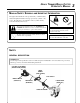
DECALS DEBRIS SHIELD DECAL Locate these safety decals on your unit. The complete unit illustration, found in the "DESCRIPTION" section, will help you locate them. Make sure the decals are legible and that you understand and follow the instructions on them. If a decal cannot be read, a new one can be ordered from your ECHO dealer. See PARTS ORDERING instructions for specific information.
GRASS TRIMMER/BRUSH CUTTER OPERATOR'S MANUAL EQUIPMENT Before operation a complete check of the unit must be performed; • Check unit for loose/missing nuts, bolts and screws. Tighten and/or replace as needed. • Inspect fuel lines, tank and area around carburetor for fuel leaks. DO NOT operate unit if leaks are found. • Inspect shield for damage and ensure that the cut-off knife is securely in place. Replace if either is damaged or missing.
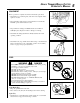
PERSONAL CONDITION AND SAFETY EQUIPMENT WARNING DANGER Trimmer/Brush Cutter users risk injury to themselves and others if the trimmer/brush cutter is used improperly and or safety precautions are not followed. Proper clothing and safety gear must be worn when operating a trimmer. Physical Condition -Your judgment and physical dexterity may not be good: - if you are tired or sick, - if you are taking medication, - if you have taken alcohol or drugs.
GRASS TRIMMER/BRUSH CUTTER OPERATOR'S MANUAL SAFE OPERATION Determine Operation Area - Provide all operators of this equipment with the operator's manual and instructions for safe operation. - Review the area to be trimmed. Look for hazards that could contribute to unsafe conditions. - Spectators and fellow workers must be warned, and children and animals prevented from coming nearer than 15M (50 ft.) while the trimmer is in use.
EXTENDED OPERATION/EXTREME CONDITIONS Vibration and Cold -It is believed that a condition called Raynaud’s Phenomenon, which affects the fingers of certain individuals may be brought about by exposure to vibration and cold. Exposure to vibration and cold may cause tingling and burning sensations followed by loss of color and numbness in the fingers. The following precautions are strongly recommended because the minimum exposure which might trigger the ailment is unknown.
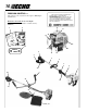
GRASS TRIMMER/BRUSH CUTTER OPERATOR'S MANUAL 9 DESCRIPTION The ECHO product you purchased has been factory pre-assembled for your convenience. Due to packaging restrictions, shield installation and other assembly may be necessary. After opening the carton, check for damage. Immediately notify your retailer or ECHO Dealer of damaged or missing parts. Use the contents list to check for missing parts.
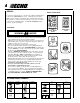
EMISSION CONTROL -- IMPORTANT ENGINE INFORMATION ENGINE FAMILY : TEH021UB24RA DISPLACEMENT : 21.2cc THIS ENGINE MEETS U.S. EPA PHI AND 1995 1999 CALIFORNIA EMISSION REGULATIONS FOR ULGE ENGINES. REFER TO OWNER’S MANUAL FOR MAINTENANCE SPECIFICATIONS AND ADJUSTMENTS. The emission control system for this engine is EM (Engine Modification). Emission Control Label located on Engine (EXAMPLE ONLY, information on label varies by FAMILY).
GRASS TRIMMER/BRUSH CUTTER OPERATOR'S MANUAL 11 1. OPERATOR'S MANUAL - Included in plastic bag (co-pack). Read before operation and keep in a safe place for future reference, i.e., operation, maintenance, storage and specifications. 2. SAFETY MANUAL - Included in plastic bag (co-pack). Read before operation and keep in a safe place for future reference to learn proper, safe operating techniques. 3. POWER HEAD - Includes the Engine, Clutch, Fuel System, Ignition System and Recoil Starter. 4.
SPECIFICATIONS SRM-2100, 2110 1/1E MOD EL 2100 1/1E 2110 1/1E Length 1500 mm (59 i n.) 1500 mm (59 i n.) Wi dth 330 mm (13.0 i n.) 600 mm (23.6 i n.) Hei ght 300 mm (11.8 i n.) 360 mm (14.2 i n.) 5.2 kg (11.4 lb.) 5.8 kg (12.7 lb.) Wei ght (dry) w/cutter head Engi ne Type Ai r cooled, two-stroke, si ngle cyli nder gasoli ne engi ne Bore Stroke D i splacement 32.2 mm (1.268 i n.) 32.2 mm (1.268 i n.) 26.0 mm (1.04 i n.) 26.0 mm (1.04 i n.) 21.2 cc (1.29 cu. i n.) 21.2 cc (1.29 cu.
GRASS TRIMMER/BRUSH CUTTER OPERATOR'S MANUAL ASSEMBLY WARNING DANGER Use only ECHO approved attachments for these models. Serious injury may result from the use of non approved attachment combinations. Read and comply with all safety instructions listed in this manual and attachment manual. ECHO, INC. will not be responsible for the failure of cutting devices, attachments or accessories which have not been tested and approved by ECHO for use with these units.
BLADE INSTALLATION All Models. IMPORTANT If non-standard monofilament head, METAL/PLASTIC blade or cultivator etc. is used, THE CARBURETOR MUST BE RE-SET or serious engine damage may occur. See "Carburetor Adjustment" pages 29 - 30 and "Specifications" page 12 of this manual. WARNING DANGER You must install a U-Handle Kit and Blade Conversion kit before operating this unit using metal blades, otherwise serious injury may result.
GRASS TRIMMER/BRUSH CUTTER OPERATOR'S MANUAL 15 Install Harness Clamp NOTE Some models require installation of Harness Clamp. If your unit does not have a clamp, follow these directions. Tools Required: Screwdriver, 8mm x 10mm Open End Wrench. Parts Required: Clamp, 4mm x 18mm Hexagon Head, Bolt, Link. 6. Remove shield and gear housing as an assembly. a. Loosen two (2) screws that clamp the gear housing to the drive shaft housing. b. Remove locating screw found at the top of the gear housing.
THROTTLE LINKAGE AND IGNITION LEADS B Tools Required: 8mm x 10mm open end wrench (all models), 3mm Allen Wrench. 1. Close choke and remove air filter cover. 2. Loosen nut (A) and place threaded end of throttle linkage in bracket slot. Finger tighten nut (A). 3. Place inner cable in slot of carburetor swivel (B) and tighten nut (A). 4. Check throttle for freedom of movement and make sure it returns to idle position.
GRASS TRIMMER/BRUSH CUTTER OPERATOR'S MANUAL 17 U-HANDLE INSTALLATION Tools Required: 8mm x 10mm Open End Wrench, Slotted Screwdriver, (3mm Hex Wrench SRM-2100 only.) Parts Required: U-Handle Kit. (SRM-2100) P/N 35130454130 NOTE On model SRM-2110 use Steps 1, 10, 11 and 13 - 17 only. 1. Close choke and remove air filter cover. 2. Disconnect ignition stop leads (C). 3. Remove inner throttle linkage from carburetor swivel (B). 4. Loosen nut (A) and remove throttle linkage from bracket. D 5.
11. Secure throttle linkage and leads to drive shaft with cable clips supplied. 12.Install power head and align gear box, power head and U-handles. Tighten all screws. 13. Place throttle linkage in slot in bracket with one nut (A) and washer on each side of bracket. Finger tighten both nuts (A). 14.Attach inner throttle cable to swivel (B). Check throttle for freedom of movement and that wide open throttle / low idle extremes are adjusted properly.
GRASS TRIMMER/BRUSH CUTTER OPERATOR'S MANUAL PRE - OPERATION OPERATION WITH BLADES Preparing the Trimmer/Brush Cutter for Blade Use WARNING DANGER Blade use DEMANDS specific Brush Cutter configuration. Operation without specified shield and harness can result in serious personal injury. Plastic and Nylon Blades Require "Blade Conversion Kit," P/N 99922200410 (metal shield and shoulder harness). Steel/Metal Blades Require "Blade Conversion Kit" PLUS a "U-Handle Kit.
8 Tooth Weed/Grass Blade P/N 69600120331 is designed for grass, garden debris and thick weeds. DO NOT use this blade for brush or heavy woody growth, 3/4" in. (19 mm) diameter or larger. Brush/Clearing Blade P/N 69500120331 is designed for cutting brush and woody growth up to 76 mm (3" in.) diameter. Use Shoulder/Waist Harness P/N 99944200200 Use of the Shoulder/ Waist Harness is recommended for ALL Trimmer/Brush Cutter use, not just Blade operation.
GRASS TRIMMER/BRUSH CUTTER OPERATOR'S MANUAL FUEL Fuel Requirements Gasoline - Use 89 Octane [R +2 M ] gasoline or gasohol known to be good quality. Gasohol may contain up to 10% Ethyl (grain) alcohol or 15% MTBE (methyl tertiary-butyl ether). Gasohol containing methyl (wood) alcohol is NOT approved. Two Stroke Oil - A two-stroke engine oil meeting ISO-L-EGD Standard (ISO/CD 13738), must be used. Echo brand Premium 50:1 oil meets this standard.
IMPORTANT Stored fuel ages. Do not mix more fuel than you expect to use in thirty (30) days, ninety (90) days when a fuel stabilizer is added. IMPORTANT Stored two-stroke fuel may separate. ALWAYS shake fuel container thoroughly before each use. EQUIPMENT CHECK Before operation a complete check of the unit must be performed; • Check unit for loose/missing nuts, bolts and screws. Tighten and/or replace as needed. • Inspect fuel lines, tank and area around carburetor for fuel leaks.
GRASS TRIMMER/BRUSH CUTTER OPERATOR'S MANUAL OPERATION - Provide all operators of this equipment with the Operator's Manual and instructions for safe operation. - Before starting the unit, equip yourself and any other person working within the 15M (50 ft.) Safety Zone with the required Protective Equipment and clothing. - During operation, the complete unit, especially the drive shaft housing and the bearing housing may become very hot, too hot to touch. Avoid contact during and immediately after operation.
5. After engine fires (or five [5] pulls) move choke lever to “Run” position. Hold throttle trigger fully depressed and pull recoil starter handle/rope (D) until engine starts and runs. Release throttle trigger and allow unit to warm up at idle for several minutes. NOTE If engine does not start with choke in “Run” position after 4 pulls, repeat instructions. D 6. After engine warm up, gradually depress throttle trigger to increase engine RPM to operating speed.
GRASS TRIMMER/BRUSH CUTTER OPERATOR'S MANUAL 25 MAINTENANCE Your ECHO unit is designed to provide many hours of trouble free service. Regular scheduled maintenance will help your unit achieve that goal. If you are unsure or are not equipped with the necessary tools, you may want to take your unit to an ECHO Service Dealer for maintenance. To help you decide whether you want to DO-IT-YOURSELF or have the ECHO Dealer do it, each maintenance task has been graded.
AIR FILTER Level 1. Tools required: Cleaning Brush Parts required: 90008 REPOWER AIR & FUEL FILTER KIT. 1. Close choke (Cold Start Position). This prevents dirt from entering the carburetor throat when the air filter is removed. Brush accumulated dirt from the air cleaner area. 2. Remove the air cleaner cover. Clean and inspect the element for damage. If element is fuel soaked and very dirty, replace. 3.
GRASS TRIMMER/BRUSH CUTTER OPERATOR'S MANUAL SPARK PLUG Level 2. Tools required: Scrench (combination socket wrench and screw driver supplied with unit), Feeler gauge (preferably a wire gauge), Soft metal brush Parts Required: Spark Plug NGK BPMR-7A 1. Remove spark plug and check for fouling, worn and rounded center electrode. 2. Clean the plug or replace with a new one. DO NOT sand blast to clean. Remaining sand will damage engine. 3. Adjust spark plug gap by bending outer electrode. 4.
NOTE The throttle linkage remains assembled to the cover and the spark plug lead and grommet remain installed. 3. Use the wooden stick or brush to remove dirt form cylinder fins. 4. Remove grass and leaves from the grid between the recoil starter and fuel tank. 5. Assemble components in reverse order. NOTE When installing the cover, be certain the tab of the metal deflector shield is in the slot of the engine cover. EXHAUST SYSTEM Spark Arrestor Screen Level 2.
GRASS TRIMMER/BRUSH CUTTER OPERATOR'S MANUAL CARBURETOR ADJUSTMENT Type 1E Emission Models Level 2. Tools required: Slotted Screwdriver w/2 mm blade width, Tachometer (ECHO P/N 99051130017) Parts required: None. NOTE Every unit is run at the factory and the carburetor is set in compliance with EPA Phase 1 and California Emission Regulations. In addition, the carburetor is equipped with HI and LO needle adjustment limiters that prevent settings outside acceptable limits. 1.
CARBURETOR ADJUSTMENT Type 1 Non Emission Models Idle Speed Adjustment NOTE If carburetor has limiter caps follow "Carburetor Adjustment" procedures for Type 1E models on previous page. Turn "idle" speed adjustment screw (C) CW (clockwise) until cutting attachment begins to turn, then turn screw out CCW (counter clockwise) until attachment stops turning. Turn screw out, CCW an additional 1/4 turn. Basic Setting 1.
GRASS TRIMMER/BRUSH CUTTER OPERATOR'S MANUAL LUBRICATION Level 1. Tools required: 8 mm Open End Wrench, Cross Head Screwdriver, Clean rag Parts Required: Lithium Base Grease. Gear Housing 1. Clean all loose debris from gear box. 2. Remove plug (A) and check level of grease. 3. Add grease if necessary, DO NOT over fill. A Drive Shaft 1. Loosen two (2) screws (B) and remove center locating screw (C). Pull gear box and shield from drive shaft housing. 2.
1. Hold drum (A) and turn spool (B) CW (clockwise) until it stops. Pull spool from drum. DO NOT push in on spool when turning. 2. Use one piece of new nylon line (C) 40 ft. (12m) long and thread through the molded loop (D) on the spool. Pull line tight and adjust so one end is 15 cm (6 in.) longer than the other. A B D C 3. Hold the spool, opening toward you. Place index finger between the two strands and wind line, tightly and evenly, in direction of arrow marked "CC". 4.
GRASS TRIMMER/BRUSH CUTTER OPERATOR'S MANUAL SHARPENING METAL BLADES Three styles of metal blades are approved for use on the ECHO Brush Cutter. The 8-tooth blade can be sharpened during normal maintenance. The clearing blade and 80 tooth blade require professional service. Before sharpening, CLOSELY inspect blade for cracks (look at the bottom of each tooth and the center mounting hole closely), missing teeth and bending. If ANY of these problems are discovered, replace the blade.
TROUBLESHOOTING Problem Engine starts hard does not start Engine Cranks Cause Remedy Fuel strainer clogged Fuel line clogged Carburetor Carburetor Clean Clean See your Echo dealer See your Echo dealer Muffler wet with fuel Fuel mixture is too rich Spark at end of plug wire No spark at end of plug wire Stop switch off Electrical problem Interlock switch Open choke Clean/replace air filter Adjust carburetor See your Echo dealer Turn switch on See your Echo dealer See your Echo dealer Spark at pl
GRASS TRIMMER/BRUSH CUTTER OPERATOR'S MANUAL STORAGE Long term storage (over 30 days) Do not store your unit for a prolonged period of time (30 days or longer) without performing protective storage maintenance which includes the following: 1. Store unit in a dry, dust free place, out of the reach of children. WARNIG DANGER Do not store in enclosure where fuel fumes may accumulate or reach an open flame or spark. 2. Place the stop switch button (A) in the "OFF" position. 3.
SERVICING INFORMATION PARTS -- Genuine ECHO Parts and ECHO REPPWER Parts and Assemblies for your ECHO products are available only from an Authorized ECHO Dealer. When you do need to buy parts always have the Model Number, Type number and Serial Number of the unit with you. You can find all three numbers on the engine housing. For future reference, write them in the space provided below. Model No. ____________ Type No. ____________ SN.