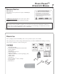
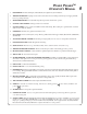
POWER PRUNERTM OPERATOR'S MANUAL Power Pruner TM Operator's Manual MODEL: PPT-260 Serial Number 07001001 - 07001230 WARNING DANGER Read rules for safe operation and instructions carefully. ECHO provides an Operator's Manual and a Safety Manual. Both must be read and understood for proper and safe operation.
INTRODUCTION Welcome to the ECHO family. This ECHO product was designed and manufactured to provide long life and on-the-job dependability. Read and understand this manual and the SAFETY MANUAL you found in the same package. You will find both easy to use and full of helpful operating tips and SAFETY messages. THE OPERATOR'S MANUAL Read and understand this manual before operation. Keep it in a safe place for future refenence.
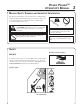
POWER PRUNERTM OPERATOR'S MANUAL MANUAL SAFETY SYMBOLS AND IMPORTANT INFORMATION Throughout this manual and on the product itself, you will find safety alerts and helpful, informational messages preceded by symbols or key words. The following is an explanation of those symbols and key words and what they mean to you. This symbol accompanied by the words WARNING and DANGER calls attention to an act or condition that can lead to serious personal injury to operator and bystanders.
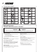
INTERNATIONAL SYMBOLS Symbol form/shape Symbol description/application Symbol form/shape Symbol description/application Read and understand Operator's Manual. Fuel and oil mixture Wear eyes, ears and head protection Finger Severing Symbol form/shape DO NOT allow flames or sparks near fuel. Emergency stop Wear hand protection. Use two handed. Hot Surface Chain lubrication DO NOT smoke near fuel. Safety/Alert Avoid all power lines. This unit is not insulated against electrical current.
POWER PRUNERTM OPERATOR'S MANUAL EXTENDED OPERATION/EXTREME CONDITIONS Vibration and Cold It is believed that a condition called Raynaud’s Phenomenon, which affects the fingers of certain individuals, may be brought about by exposure to vibration and cold. Exposure to vibration and cold may cause tingling and burning sensations, followed by loss of color and numbness in the fingers. The following precautions are strongly recommended, because the minimum exposure which might trigger the ailment is unknown.
SAFE OPERATION WARNING DANGER All overhead electrical conductors and communications wires can have electricity flow with high voltages. Never touch wires directly or indirectly when pruning, otherwise serious injury or death may result. WARNING DANGER Do not operate this product indoors or in inadequately ventilated areas. Engine exhaust contains poisonous emissions and can cause serious injury or death.
POWER PRUNERTM OPERATOR'S MANUAL EMISSION CONTROL EPA Phase 2 The emission control system for these engines are EM (Engine Modification). IMPORTANT ENGINE INFORMATION ENGINE FAMILY: 3EHXS.0254EA DISPLACEMENT: 25.4 CC THIS ENGINE MEETS U.S. EPA PHASE 2 EMISSION THIS ENGINE MEETS U.S. EPA PHASE II EMISSION REGULATIONS FOR SMALL NONROAD ENGINE. REFER TO OWNER'S MANUAL FOR MAINTENANCE SPECIFICATIONS AND ADJUSTMENTS. An Emission Control Label is located on the engine.
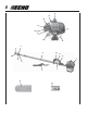
13 21 20 19 14 18 17 16 15 8 7 9 10 6 11 12 1 5 4 2 3 22 23
POWER PRUNERTM OPERATOR'S MANUAL 1. POWER HEAD - Includes the Engine, Clutch, Fuel System, Ignition System and Starter. 2. THROTTLE TRIGGER - Spring loaded to return to idle when released. During acceleration press trigger gradually for best operating technique. 3. SHOULDER HARNESS - An adjustable strap that suspends the unit from the operator. 4. CUTTING ATTACHMENT - Sealed, gear ratio is 1.5:1 reduction. 5. CUTTING SHOE - Used to capture and stabilize branch while cutting.
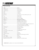
SPECIFICATIONS MODEL ----------------------------------------------------- PPT-260 Length (Standard) ----------------------------------------- 2.76 m (9 ft. 1 in.) Length (Extended) ----------------------------------------- 3.90 m (12 ft. 10 in.) Length w/extension ---------------------------------------- 5.44 m (17 ft. 10 in.) Width -------------------------------------------------------- .23 m (9.06 in.) Height ------------------------------------------------------- .22 m (8.7 in.
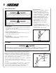
POWER PRUNERTM OPERATOR'S MANUAL ASSEMBLY Tools Required: 10x19mm (13/32x3/4in) T-wrench, 3 & 4 mm Hex Wrench Parts Required: Power Head, Drive Shaft Assembly, Cutting Attachment DRIVE SHAFT / POWER HEAD 1. Loosen bolt (A). 2. Match square socket in engine shaft with square power transmission shaft (B) and slide together until engine rests against the machine surface of lower drive shaft coupler (C). B A 3. 4. Rotate lower drive shaft to align engine and rear handle assembly in an upright position.
2. Loosen center clamp knob (F) turning counter clockwise. G 3. Pull upper tube (G) out of fiberglass lower tube 127-152 mm (5-6 in.), then slide (G) back into fiberglass lower tube exposing inner drive shaft (H). Align and join star shaped drive end of inner drive shaft (H) with cutting attachment shaft (I). 4. Align ridges on upper tube (G) with seams in cutting attachment. 5. F H G G Slide together aligning locator screw (E) in cutting attachment with locating hole (J) in upper tube.
POWER PRUNERTM OPERATOR'S MANUAL SAW CHAIN TENSION ADJUSTMENT WARNING DANGER Always disconnect spark plug wire before servicing cutting attachment. Wear gloves when handling saw chain, otherwise serious personal injury may result. To Adjust Saw Chain Tension. B 1. Loosen two (2) 10 mm (13/32 in.) guide bar nuts (A) located on cutting attachment. 2. Turn the adjuster slot (B) clockwise until saw chain touches the bottom of guide bar.
PRE-OPERATION FUEL Fuel Requirements Gasoline - Use 89 Octane [R+M/2] (mid grade or higher) gasoline known to be good quality. Gasoline may contain up to 15% MTBE (methyl tertiary-butyl ether). Gasohol containing methyl (wood) alcohol is NOT approved. Two Stroke Oil - A two-stroke engine oil meeting ISO-L-EGD (ISO/CD 13738) and J.A.S.O. FC Standards must be used. Echo brand premium Power Blend TM Universal 2-Stroke Oil meets these standards.
POWER PRUNERTM OPERATOR'S MANUAL LUBRICATING THE GUIDE BAR AND SAW CHAIN Automatic Oiling System 1. Wipe debris from around oil fill cap. 2. Remove oil fill cap and fill reservoir with a quality, low viscosity guide bar and saw chain oil. NOTE The discharge volume of the automatic oiler is preset to deliver 3 to 4 cc/min. at normal operating RPM. During heavy or dry cutting conditions the oil discharge volume may be adjusted to assure adequate lubrication. Refill the oil reservoir with each tank of fuel.
OPERATION STARTING COLD ENGINE WARNING DANGER A The attachment will operate immediately when the engine starts and could result in loss of control and possible serious injury. Keep movable parts of the attachment off the ground and away from objects that could become entangled or thrown. 1. Stop Switch Move stop switch button (A) forward away from the STOP position. 2. Choke Move choke (B) to “Cold Start” ( ) Position. B 3. 4. 5.
POWER PRUNERTM OPERATOR'S MANUAL STARTING WARM ENGINE The starting procedure is the same as Cold Start except DO NOT close the choke, and do not depress throttle trigger to wide open position. WARNING DANGER The attachment should not move at idle, otherwise serious personal injury may result. A NOTE If attachment moves, readjust carburetor according to “Carburetor Adjustment” instructions in this manual or see your ECHO Dealer. 1. Stop Switch.
STOPPING ENGINE 1. Throttle. Release throttle trigger, and allow engine to return to idle before stopping engine. 2. A Stop Switch. Move stop switch button (A) backward to STOP position. WARNING DANGER If engine does not stop when stop switch is moved to STOP position, close choke - COLD START position - to stall engine. Have your ECHO dealer repair stop switch before using pruner again.
POWER PRUNERTM OPERATOR'S MANUAL 19 MAINTENANCE Your ECHO Power PrunerTM is designed to provide many hours of trouble free service. Regular scheduled maintenance will help your pruner achieve that goal. If you are unsure or are not equipped with the necessary tools, you may want to take your unit to an ECHO Service Dealer for maintenance. To help you decide whether you want to DO-IT-YOURSELF or have the ECHO Dealer do it, each maintenance task has been graded.
AIR FILTER Level 1. Tools required: Cleaning brush 25 or 50 mm (1 or 2 in.) Parts required: 90030 REPOWERTM Air and Fuel Filter Kit 1. ]). This prevents dirt from Close choke (Cold Start Position [ entering the carburetor throat when the air filter is removed. Brush accumulated dirt from the air cleaner area. 2. Remove the air cleaner cover. Clean and inspect the element for damage. If element is fuel soaked and very dirty, replace. 3.
POWER PRUNERTM OPERATOR'S MANUAL SPARK PLUG Level 2. Tools required: 10x19mm (13/32x3/4in) T-wrench, Feeler gauge, Soft metal brush Parts Required: Spark Plug, NGK BPMR-8Y P/N A42500000 1. Remove spark plug and check for fouling, worn and rounded center electrode. 2. Clean the plug or replace with a new one. DO NOT sand blast to clean. Remaining sand will damage engine. 3. Adjust spark plug gap by bending outer electrode. 4. Tighten spark plug to 145-155 kg/cm (125-135 in. lb.).
1. Remove spark plug lead. 2. Remove two (2) muffler cover screws and muffler cover (A). 3. Remove screw and arm rest (B). 4. Remove engine cover (C). IMPORTANT DO NOT use a metal scraper to remove dirt from the cylinder fins. 5. Use brush to remove dirt from the cylinder fins. 6. Remove grass and leaves from the grid between the recoil starter and fuel tank. 7. Assemble components in reverse order. EXHAUST SYSTEM Spark Arrestor Screen Level 2.
POWER PRUNERTM OPERATOR'S MANUAL 1. Remove spark plug lead. 2. Remove muffler cover (A). 3. Place piston at Top Dead Center (TDC) to prevent carbon/dirt from entering cylinder. 4. Remove spark arrestor screen cover (B), gasket (C), and screen (D) from muffler body. 5. Clean carbon deposits from muffler components. A D 6. 7. Replace screen if it is cracked, plugged or has holes burned through. Assemble components in reverse order. Cylinder Exhaust Port Level 3.
NOTE Every unit is run at the factory and the carburetor is set in compliance with emission regulations. This carburetor does not have acceleration and high speed adjustment needles. 1. Check idle speed and reset if necessary. If a tachometer is available, idle speed screw (A) should be set to the specifications found on page 10 "Specifications" of this manual. Turn idle screw (A) clockwise to increase idle speed; counter clockwise to decrease idle speed.
POWER PRUNERTM OPERATOR'S MANUAL 25 FILING SAW CHAIN Level 3. Tools required: 4.5 mm round File P/N 89751001130, Flat File P/N 89751100230, Depth Gauge P/N 89751400232. IMPORTANT Dull or damaged cutters will result in poor cutting performance, increased vibration and premature saw chain failure. WARNING DANGER Always stop engine and disconnect spark plug wire before servicing guide bar and saw chain. Always wear gloves when filing saw chain, otherwise serious personal injury may result. 1.
TROUBLESHOOTING ENGINE PROBLEM TROUBLESHOOTING CHART Problem C h eck Status Fuel at carburetor No fuel at carburetor Engine runs, but dies or does not accelerate properly Engine does not crank Remedy Fuel strainer clogged Fuel line clogged Carburetor Clean or replace Clean or replace See your Echo dealer Carburetor See your Echo dealer Fuel Mixture too rich Open choke Clean/replace air filter Adjust carburetor See your Echo dealer No spark Stop switch off Electrical problem Interlock switc
POWER PRUNERTM OPERATOR'S MANUAL 27 STORAGE WARNING DANGER During operation the muffler or catalytic muffler and surrounding cover become hot. Always keep exhaust area clear of flammable debris during transportation or when storing, otherwise serious property damage or personal injury may result. Long Term Storage (over 30 days) Do not store your unit for a prolonged period of time (30 days or longer) without performing protective storage maintenance which includes the following: 1.
SERVICING INFORMATION PARTS Genuine ECHO Parts and ECHO REPOWER™ Parts and Assemblies for your ECHO products are available only from an Authorized ECHO Dealer. When you do need to buy parts always have the Model Number and Serial Number of the unit with you. You can find these numbers on the engine housing. For future reference, write them in the space provided below. Model No. _____________ SN. ____________ DEALER? Call 1-800-432-ECHO or www.echo-usa.
This Supplement contains important information. Please keep with your Operator's Manual. SUPPLEMENT TO OPERATOR'S MANUAL FOR MODELS: SRM-260/260S HCA-260 PAS-260 PE-260 PPT-260 SHC-260 SERIAL NUMBER 05001001 - 05999999 SERIAL NUMBER 07001001 - 07999999 Serial number range on owner’s manual cover may be different than serial number on unit. Sections listed below have been modified for units serial number 06001001 & up.
ECHO CONSUMER PRODUCT SUPPORT If you require assistance or have questions concerning the application, operation or maintenance of this product you may call the ECHO Consumer Product Support Department at 1-800-673-1558 from 8:30 am to 4:30 pm (Central Standard Time) Monday through Friday. Before calling, please know the model and serial number of your unit to help your Consumer Product Support Representative.