
User manual


Table Of Contents
- Introduction
- Table of Contents
- Safety
- Emission Control (exhaust & evaporative)
- Description
- Contents
- Assembly
- cutting attachment to drive shaft installation
- saw chain tension adjustment
- Operation
- fuel
- lubricating the guide bar and saw chain
- adjusting automatic oiler
- starting cold engine
- starting warm engine
- stopping engine
- pruning techniques
- Maintenance
- air filter
- fuel filter
- spark plug
- cooling system cleaning
- exhaust system
- carburetor adjustment
- guide bar and saw chain replacement
- filing saw chain
- Troubleshooting
- Storage
- Specifications
- Warranty Statements
- Servicing Information
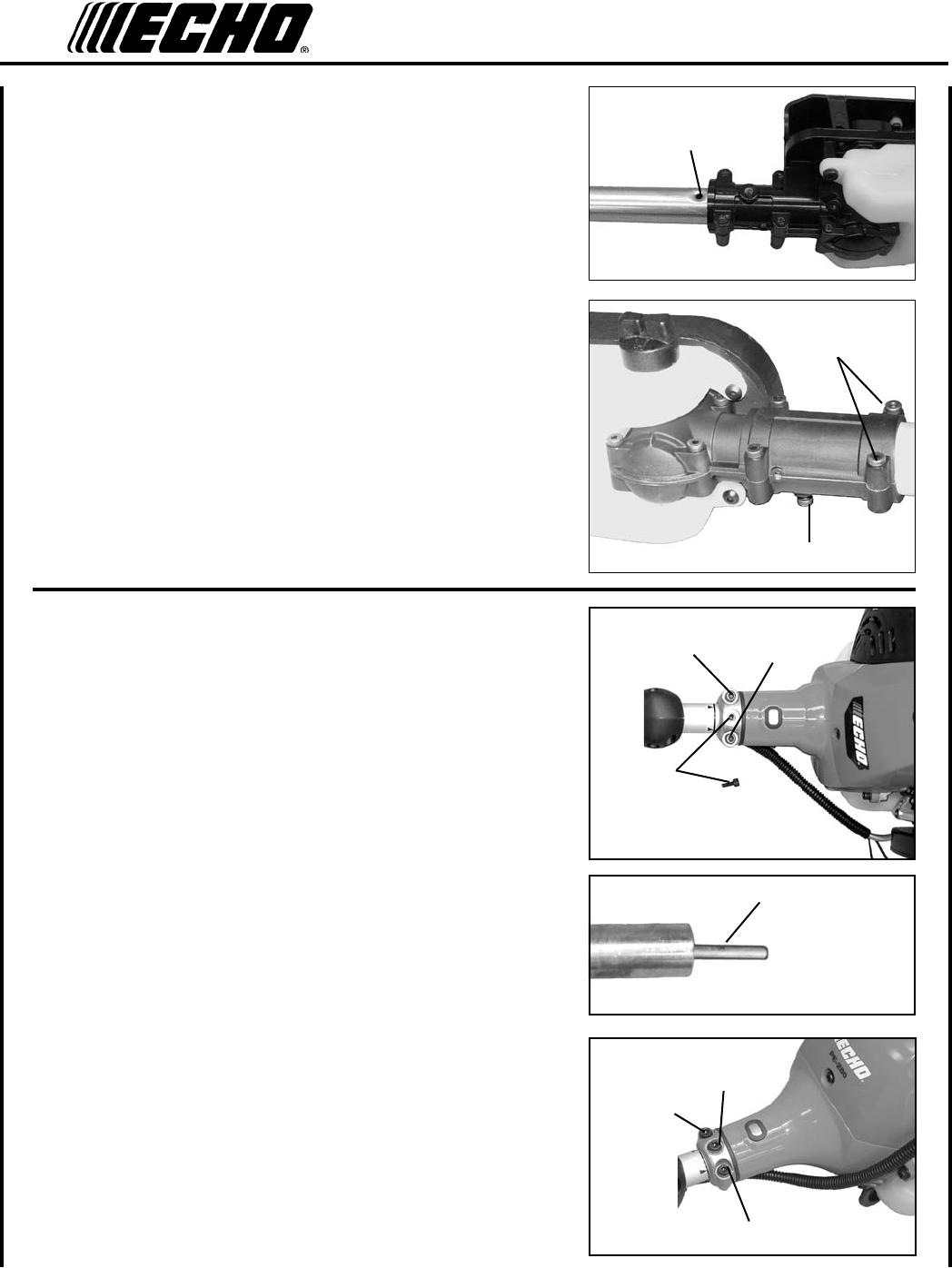
12
2. Slide the cutting attachment onto the shaft housing until the hole
in the neck of the cutting attachment is aligned with the hole (C) in
the housing. (It may be necessary to rotate the saw chain slightly
to align the internal pinion and drive shaft.)
3. Insert locator screw (B) into hole (C) and tighten to snug.
4. Tighten bolts (A), clamping the cutting attachment onto the hous-
ing.
b
c
a
drIve shaft / power head
1. Loosen two (2) clamping screws (A) and remove locating screw
(B).
2. Pull exible drive shaft (C) 2-3 in. out of drive shaft assembly.
3. Align exible drive shaft with engine socket and slide together un-
til locating hole in shaft is visible through locating hole in engine
housing.
4. Install locating screw (B) and tighten clamping bolts (A).
B
A
A
B
A
A
C