Grass Trimmer Operator's Manual MODEL GT-2000R Type 1E Serial Number 001001 & Up WARNING DANGER Read rules for safe operation and instructions carefully. ECHO provides an Operator's Manual and a Safety Manual. Both must be read and understood for proper and safe operation.
INTRODUCTION Welcome to the ECHO family. This ECHO product was designed and manufactured to provide long life and on-thejob-dependability. Read and understand this manual and the SAFETY MANUAL you found in the same package. You will find both easy to use and full of helpful operations tips and SAFETY messages. THE OPERATOR'S MANUAL Read and understand this manual before operation. Keep it in a safe place for future reference.
GRASS TRIMMER OPERATOR'S MANUAL MANUALSAFETY SYMBOLS AND IMPORTANT INFORMATION Throughout this manual and on the product itself, you will find safety alerts and helpful, information messages preceded by symbols or key words. The following is an explanation of those symbols and key words and what they mean to you. This symbol accompanied by the words WARNING and DANGER calls attention to an act or condition that can lead to serious personal injury to operator and bystanders.
INTERNATIONAL SYMBOLS SYMBOL FORM/ SHAPE SYMBOL DESCRIPTION/APPLICATION SYMBOL FORM/ SHAPE Read and understand Operator's Manual. SYMBOL DESCRIPTION/APPLICATION SYMBOL FORM/ SHAPE FUEL AND OIL MIXTURE WEAR EYES, EARS AND HEAD PROTECTION FINGER SEVERING WEAR SLIP RESISTANT FOOT WEAR. HOT SURFACE KEEP BYSTANDERS AND HELPERS AWAY 15 M (50 FT.). SYMBOL DESCRIPTION/APPLICATION EMERGENCY STOP Engine choke control.
GRASS TRIMMER OPERATOR'S MANUAL EXTENDED OPERATION/EXTREME CONDITIONS Vibration and Cold It is believed that a condition called Raynaud’s Phenomenon, which affects the fingers of certain individuals, may be brought about by exposure to vibration and cold. Exposure to vibration and cold may cause tingling and burning sensations, followed by loss of color and numbness in the fingers. The following precautions are strongly recommended, because the minimum exposure which might trigger the ailment is unknown.
SAFE OPERATION WARNING DANGER Do not operate this product indoors or in inadequately ventilated areas. Engine exhaust contains poisonous emissions and can cause serious injury or death. • Provide all operators of this equipment with the Operator's Manual and instructions for safe operation. Keep A Firm Grip • Hold the front and rear handles with both hands with thumbs and fingers encircling the handles Keep A Solid Stance • Maintain footing and balance at all times.
GRASS TRIMMER OPERATOR'S MANUAL 7 CONTENT LIST ____ 1 ____ ____ ____ 1 ____ ____ ____ ____ ____ ____ ____ ____ ____ ____ ____ ____ ____ ____ ____ ____ ____ - - - Trimmer Assembly Power Head Drive Shaft Assembly Plastic Bag (Co-Pack) Rapid LoaderTM 2-line Head Operator's Manual Safety Manual Shield Assembly Shield Mount Hardware -1, 1/4-20 bolt -1, 1/4-20 wing nut -1, 1/4-20 flat washer Line Head Mount Hardware -1, 3/8-24 Locknut -1, Small Washer -1, Large Washer -12, 8 in. X .
1. POWER HEAD - Factory Assembled to the Driveshaft assembly. Includes the Engine, Clutch, Fuel System, Ignition System and Recoil Starter. 2. GRIP - Rear (right hand) handle. 3. FRONT HANDLE - The Front (loop) handle is factory assembled to the Drive Shaft assembly but must be repositioned for proper cutting attitude and operator comfort. 4. DRIVESHAFT ASSEMBLY - Factory Assembled to the Power Head.
GRASS TRIMMER OPERATOR'S MANUAL SPECIFICATIONS MOD EL GT-2000R Length 1400 mm (55.1 i n.) Wi dth 330 mm (13.0 i n.) Hei ght 360 mm (14.2 i n.) Wei ght (dry) w/C utter Head Engi ne Type Bore Stroke D i splacement Exhaust System 4.08 kg (9.0 lb.) Ai r cooled, two-stroke, si ngle cyli nder gasoli ne engi ne 32.2 mm (1.268 i n.) 26.0 mm (1.04 i n.) 21.2 cc (1.29 cu. i n.
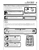
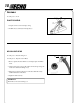
ASSEMBLY Tools Required: None PLASTIC SHIELD 1. Snap the shield over the bearing housing. 2. Install bolt (A), washer (B) and wing nut (C). NYLON LINE HEAD Tools Required: Head Locking Tool Parts Required: Rapid LoaderTM Head. 1. Remove plastic threaded shaft sleeve and adapter plate from PTO shaft. 2. Align locating hole in upper plate with hole in bearing housing and insert 1/8 in. diameter locking tool (A). 3.
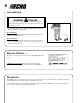
GRASS TRIMMER OPERATOR'S MANUAL NYLON LINE INSTALLATION Level 1. Tools Required: None Parts Required: Two (2) Pre-cut Nylon Line 8 in. X .080 in. 1. Shut engine off. Lay unit on the ground with head assembly up. 2. Remove old nylon line through center recess of head. 3. Thread new lines through outside holes (A) in housing until ends meet in center of recess. A NOTE Insert cutting line ends to center of head recess to insure easy removal of used lines.
PRE - OPERATION FUEL Fuel Requirements Gasoline - Use 89 Octane [ R + M ] (mid grade or higher) gasoline known 2 to be good quality. Gasoline may contain up to 15% MTBE (methyl tertiary-butyl ether). Gasohol containing methyl (wood) alcohol is NOT approved. Two Stroke Oil - A two-stroke engine oil meeting ISO-L-EGD Standard (ISO/CD 13738), must be used. Echo brand Premium 50:1 oil meets this standard.
GRASS TRIMMER OPERATOR'S MANUAL OPERATION STARTING COLD ENGINE WARNING DANGER The cutting attachment should not rotate at idle. If attachment rotates, readjust carburetor according to "Carburetor Adjustment" instructions in this manual or see your ECHO Dealer, otherwise serious personal injury may result. NOTE Refer to the Grass Trimmer / Brush Cutter Safety Manual for proper and safe trimming techniques. 1. Stop Switch Move stop switch button (A) away from the STOP position. 2.
STARTING WARM ENGINE WARNING DANGER The cutting attachment should not rotate at idle. If attachment rotates, readjust carburetor according to "Carburetor Adjustment" instructions in this manual or see your ECHO Dealer, otherwise serious personal injury may result. 1. Stop Switch Move stop switch button (A) away from the STOP position. 2. Recoil Starter Lay the trimmer on a flat clear area and pull the recoil starter handle (D) until the engine fires.
GRASS TRIMMER OPERATOR'S MANUAL 15 MAINTENANCE Your ECHO trimmer is designed to provide many hours of trouble free service. Regular scheduled maintenance will help your trimmer achieve that goal. If you are unsure or are not equipped with the necessary tools, you may want to take your unit to an ECHO Service Dealer for maintenance. To help you decide whether you want to DO-IT-YOURSELF or have the ECHO Dealer do it, each maintenance task has been graded.
AIR FILTER Level 1. Tools required: Cleaning brush, 25 or 50 mm (1 or 2 in.) medium bristle paint brush. Parts required: 90008 REPOWERTM AIR & FUEL FILTER KIT. 1. Close choke (Cold Start Position). This prevents dirt from entering the carburetor throat when the air filter is removed. Brush accumulated dirt from the air cleaner area. 2. Remove the air cleaner cover. Clean and inspect the element for damage. If element is fuel soaked and very dirty, replace. 3.
GRASS TRIMMER OPERATOR'S MANUAL SPARK PLUG Level 2. Tools Required: Spark Plug socket wrench and screw driver, Feeler gauge, preferably a wire gauge. Parts Required: 90064 REPOWERTM TUNE-UP KIT 1. Remove spark plug and check for fouling, worn and rounded center electrode. 2. Clean the plug or replace with a new one. DO NOT sand blast to clean. Remaining sand will damage engine. 3. Adjust spark plug gap by bending outer electrode. 4. Tighten spark plug to 145-155 kg/cm (125-135 in. lb.).
IMPORTANT DO NOT use a metal scraper to remove dirt from the cylinder fins. 3. Use the wooden stick or brush to remove dirt from the cylinder fins. 4. Remove grass and leaves from the grid between the starter and fuel tank. 5. When installing the cover, be certain the tab of the metal deflector shield is in the slot of the cover. EXHAUST SYSTEM Spark Arrestor Screen Level 2. Tools Required: Cross Head Screwdriver. Soft metal brush.
GRASS TRIMMER OPERATOR'S MANUAL CARBURETOR ADJUSTMENT Level 2. Tools required: Screwdriver, Tachometer (ECHO P/N 99051130017). Parts required: None. NOTE Every unit is run at the factory and the carburetor is set in compliance with EPA Phase 1 and California Emission Regulations. In addition, the carburetor is equipped with HI and LO needle adjustment limiters that prevent settings outside acceptable limits. 1. Before adjusting the carburetor, clean or replace the air filter and spark arrester screen. 2.
LUBRICATION Level 1. Tools Required: 8mm Open End Wrench, Screwdriver, Clean Rag. Parts Required: ECHO® LUBETM 8 oz. (P/N 91014) or Lithium Base Grease. 1. Remove plastic shield. 2. Loosen bearing housing locating screw (A), at the top of the housing, remove mounting screw (B). 3. Pull the flexible drive shaft (C) from the housing, wipe clean and recoat with a thin coating [1/2 oz. (15 ml)] of grease. 4.
GRASS TRIMMER OPERATOR'S MANUAL TROUBLESHOOTING ENGINE PROBLEM TROUBLESHOOTING CHART Problem C h eck Fuel at carburetor Engine cranks starts hard/ doesn't start Engine runs, but dies or does not accelerate properly Engine does not crank Fuel at cylinder Status C au se No fuel at carburetor Fuel strainer clogged Fuel line clogged Carburetor Remedy Clean or replace Clean or replace See your Echo dealer No fuel at cylinder Carburetor See your Echo dealer Muffler wet with fuel Fuel Mixture too ric
STORAGE Long Term Storage (over 30 days) WARNING DANGER During operation the muffler or catalytic muffler and surrounding cover become hot. Always keep exhaust area clear of flammable debris during transportation or when storing, otherwise serious property damage or personal injury may result. Do not store your unit for a prolonged period of time (30 days or longer) without performing protective storage maintenance which includes the following: 1.
GRASS TRIMMER OPERATOR'S MANUAL NOTES 23
SERVICING INFORMATION PARTS Genuine ECHO Parts and ECHO REPOWER™ Parts and Assemblies for your ECHO products are available only from an Authorized ECHO Dealer. When you do need to buy parts always have the Model Number, Type and Serial Number of the unit with you. You can find these numbers on the engine housing. For future reference, write them in the space provided below. Model No. _____________ Type _________SN.