Grass Trimmer Operator's Manual MODEL GT-200R Serial Number 05001001 - 05147300 WARNING DANGER Read rules for safe operation and instructions carefully. ECHO provides an Operator's Manual and a Safety Manual. Both must be read and understood for proper and safe operation.
INTRODUCTION Welcome to the ECHO family. This ECHO product was designed and manufactured to provide long life and on-thejob-dependability. Read and understand this manual and the SAFETY MANUAL you found in the same package. You will find both easy to use and full of helpful operations tips and SAFETY messages. THE OPERATOR'S MANUAL Read and understand this manual before operation. Keep it in a safe place for future reference.
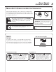
GRASS TRIMMER OPERATOR'S MANUAL MANUALSAFETY SYMBOLS AND IMPORTANT INFORMATION Throughout this manual and on the product itself, you will find safety alerts and helpful, informational messages preceded by symbols or key words. The following is an explanation of those symbols and key words and what they mean to you. This symbol accompanied by the words WARNING and DANGER calls attention to an act or condition that can lead to serious personal injury to operator and bystanders.
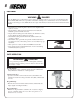
Shaft Decal P/N 89031744530 WARNING DANGER • This unit can be dangerous and cause serious injury if improperly used. To reduce injury risk to operator, helpers and bystanders, read and understand the Operator's and Safety manuals. • Blindness can occur from objects that are thrown or ricocheted even with shield in place. Operators, helpers and bystanders must wear ANSI Z87.1 approved eye protection. • Always wear hearing protection when operating unit.
GRASS TRIMMER OPERATOR'S MANUAL SAFETY INSTRUCTIONS PERSONAL CONDITION AND SAFETY EQUIPMENT WARNING DANGER Trimmer/Brush Cutter users risk injury to themselves and others if the trimmer/brush cutter is used improperly and or safety precautions are not followed. Proper clothing and safety gear must be worn when operating a trimmer.
EQUIPMENT WARNING DANGER Use only ECHO approved attachments. Serious injury may result from the use of a non approved attachment combination. ECHO, INC. will not be responsible for the failure of cutting devices, attachments or accessories which have not been tested and approved by ECHO. Read and comply with all safety instructions listed in this manual and safety manual. • Check unit for loose/missing nuts, bolts and screws. Tighten and/or replace as needed.
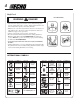
GRASS TRIMMER OPERATOR'S MANUAL EMISSION CONTROL EPA Phase 2 The emission control system for this engine is EM (Engine Modification ). An Emission Control Label is located on the engine. (This is an EXAMPLE ONLY, information on label varies by engine FAMILY). IMPORTANT ENGINE INFORMATION ENGINE FAMILY: 3EHXS.0214EA DISPLACEMENT: 21.2 CC EMISSION COMPLIANCE PERIOD : 300 HRS. THIS ENGINE MEETS U.S. EPA PHASE 2 EMISSION REGULATIONS FOR SMALL NONROAD ENGINES.
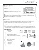
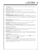
10 18 19 17 16 15 11 14 12 13 4 3 5 7 2 1 6 8 9
GRASS TRIMMER OPERATOR'S MANUAL 1. 2. 3. 4. 5. 6. 7. 8. 9. 10. 11. 12. 13. 14. 15. POWER HEAD - Factory Assembled to the Driveshaft assembly. Includes the Engine, Clutch, Fuel System, Ignition System and Recoil Starter. GRIP - Rear (right hand) handle. FRONT HANDLE - The Front (loop) handle is factory assembled to the Drive Shaft assembly but must be repositioned for proper cutting attitude and operator comfort. DRIVESHAFT ASSEMBLY - Factory Assembled to the Power Head.
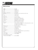
SPECIFICATIONS MODEL ------------------------------------------ GT-200R Length -------------------------------------------- 1400 mm (55.1 in.) Width --------------------------------------------- 310 mm (12.2 in.) Height -------------------------------------------- 385 mm (15.2 in.) Weight (dry) w/Cutter Head ------------------- 4.1 kg (9.04 lb.
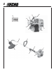
GRASS TRIMMER OPERATOR'S MANUAL ASSEMBLY Tools Required: Locking Tools (2), Wrench 17 x 14.5 (9/16 in.) Parts Required: Rapid LoaderTM Head, Large washer, Small washer, 3/8-24 Locknut, (2) Pre-cut Nylon Line 8 in. x .080 in. WARNING DANGER Cut-off knife on debris shield has sharp edges. Avoid contact when installing or removing line head. PLASTIC SHIELD INSTALLATION B 1. Remove wing nut (A), washer (B), and bolt (C). C A 2. Snap the shield over the bearing housing. 3.
NYLON LINE INSTALLATION 1. Shut engine off. Lay unit on the ground with head assembly up. 2. Remove old nylon line through center recess of head. 3. Thread new lines through outside holes (A) in housing until ends meet in center of recess. NOTE Insert cutting line ends to center of head recess to insure easy removal of used lines. A FRONT (LOOP) HANDLE NOTE Front handle is pre-installed. Re-positioning and tightening is all that is required. A 1.
GRASS TRIMMER OPERATOR'S MANUAL 13 PRE - OPERATION FUEL Fuel Requirements Gasoline - Use 89 Octane [ R + M ] (mid grade or higher) gasoline known 2 to be good quality. Gasoline may contain up to 15% MTBE (methyl tertiary-butyl ether). Gasohol containing methyl (wood) alcohol is NOT approved. Two Stroke Oil - A two-stroke engine oil meeting ISO-L-EGD (ISO/CD 13738) and J.A.S.O. FC Standards must be used. Echo brand premium Power Blend TM Universal 2-Stroke Oil meets these standards.
OPERATION STARTING COLD ENGINE WARNING DANGER The attachment will operate immediately when the engine starts and could result in loss of control and possible serious injury. Keep movable parts of the attachment off the ground and away from objects that could become entangled or thrown. 1. Stop Switch Move stop switch (A) away from the STOP position. A B 2. Choke Move choke (B) to “Cold Start” ( ) Position. 3.
GRASS TRIMMER OPERATOR'S MANUAL STARTING WARM ENGINE The starting procedure is the same as Cold Start except DO NOT close the choke, and do not depress throttle trigger to wide open position. WARNING DANGER The attachment should not move at idle, otherwise serious personal injury may result. A NOTE If attachment moves, readjust carburetor according to “Carburetor Adjustment” instructions in this manual or see your ECHO Dealer. 1. Stop Switch Move stop switch (A) away from the STOP position 2.
MAINTENANCE Your ECHO trimmer is designed to provide many hours of trouble free service. Regular scheduled maintenance will help your trimmer achieve that goal. If you are unsure or are not equipped with the necessary tools, you may want to take your unit to an ECHO Service Dealer for maintenance. To help you decide whether you want to DO-IT-YOURSELF or have the ECHO Dealer do it, each maintenance task has been graded. If the task is not listed see your Echo dealer for repairs.
GRASS TRIMMER OPERATOR'S MANUAL AIR FILTER Level 1. Tools required: 25 or 50 mm (1 or 2 in.) Cleaning brush Parts required: 90008 REPOWERTM AIR & FUEL FILTER KIT. 1. Close choke (Cold Start Position). This prevents dirt from entering the carburetor throat when the air filter is removed. Brush accumulated dirt from the air cleaner area. 2. Remove the air cleaner cover. Clean and inspect the element for damage. If element is fuel soaked and very dirty, replace. 3.
SPARK PLUG Level 2. Tools Required: Spark Plug socket wrench and screw driver, feeler gauge, soft wire brush. Parts Required: REPOWERTM Tune-Up Kit P/N 90074 1. Remove spark plug and check for fouling, worn and rounded center electrode. 2. Clean the plug or replace with a new one. DO NOT sand blast to clean. Remaining sand will damage engine. 3. Adjust spark plug gap by bending outer electrode. 4. Tighten spark plug to 145-155 kg/cm (125-135 in. lb.). 0.65 mm (0.026 in.
GRASS TRIMMER OPERATOR'S MANUAL IMPORTANT DO NOT use a metal scraper to remove dirt from the cylinder fins. 4. Use the brush to remove dirt from the cylinder fins. 5. Remove grass and leaves from the grid between the recoil starter and fuel tank. 6. Assemble components in reverse order. NOTE When installing the cover, be certain the tabs of the deflector shield are in the slot of the cover. EXHAUST SYSTEM Spark Arrestor Screen Level 2.
Cylinder Exhaust Port Level 3. IMPORTANT The cylinder exhaust port must be inspected and cleaned of excess carbon every 3 months or 90 hours of operation in order to maintain this engine within the emissions durability period. ECHO strongly recommends that you return your unit to your ECHO dealer for this important maintenance service. CARBURETOR ADJUSTMENT Engine Break-In New engines must be operated a minimum duration of two tanks of fuel break-in before carburetor adjustments can be made.
GRASS TRIMMER OPERATOR'S MANUAL LUBRICATION Level 1. Tools Required: 8mm Open end wrench, screwdriver, clean rag. Parts Required: ECHO® LUBETM 8 oz. (P/N 91014) or Lithium Base Grease. 1. Remove plastic shield. 2. Loosen bearing housing locating screw (A), at the top of the housing, loosen mounting screw (B) and remove gear case from drive housing. 3. Pull the flexible drive shaft (C) from the drive housing, wipe clean and recoat with a thin coating [1/2 oz. (15 ml)] of grease. 4.
TROUBLESHOOTING ENGINE PROBLEM TROUBLESHOOTING CHART Problem C h eck Fuel at carburetor Engine cranks starts hard/ doesn't start Fuel at cylinder Spark at end of plug wire Status No fuel at carburetor Fuel strainer clogged Fuel line clogged Carburetor Fuel filter Fuel vent Engine runs, but dies or does not accelerate properly Engine does not crank Spark Plug Carburetor Remedy Clean or replace Clean or replace See your Echo dealer No fuel at cylinder Carburetor See your Echo dealer Muffler
GRASS TRIMMER OPERATOR'S MANUAL 23 STORAGE Long Term Storage (over 30 days) WARNING DANGER During operation the muffler or catalytic muffler and surrounding cover become hot. Always keep exhaust area clear of flammable debris during transportation or when storing, otherwise serious property damage or personal injury may result. Do not store your unit for a prolonged period of time (30 days or longer) without performing protective storage maintenance which includes the following: 1.
SERVICING INFORMATION PARTS Genuine ECHO Parts and ECHO REPOWER™ Parts and Assemblies for your ECHO products are available only from an Authorized ECHO Dealer. When you do need to buy parts always have the Model Number, Type and Serial Number of the unit with you. You can find these numbers on the engine housing. For future reference, write them in the space provided below. Model No. _____________ Type _________SN.