Owners Manual v.3 User guide

4 INCH CHIPPER
6
Section
ASSEMBLY
2
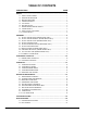
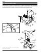
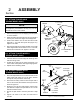
2.1 ATTACH TRAILER AXLE
(ENGINE MODEL ONLY)
1. Remove

2. 

3.         


4. 


1. Hold one wheel to a hub and align the wheel lug holes
with the hub lug holes.
2. Thread the lug bolts into the holes and tighten to 75

3. 
1. Attach
     

2. 

shown in Figure 2.2.
3. 

bolts and centerlock nuts.
4.      
pin.
5.          

FENDER
3/8” x
1-1/4” BOLT
AXLE
MOUNTING
BRACKET
3/8”
NUT
1/2” CENTERLOCK
NUT
1/2” x 1-1/4”
BOLT
1/2”
WASHER
1/2” x 3”
BOLTS
1/2” CENTER-
LOCK NUTS
SAFETY
CHAIN
JACK
STAND
SNAP
PIN
3/8” x 3-1/2”
BOLT
HITCH POLE
WELDMENT
3/8”
WASHER
3/8”
NYLOCK
NUT
COUPLER
Figure 2.2, Trailer hitch assembly
Figure 2.1, Attaching the trailer axle
NOTE
       

illustrations shown in this manual.
2.2 ATTACH TRAILER WHEELS
(ENGINE MODEL ONLY)
2.3 ATTACH TRAILER HITCH
(ENGINE MODEL ONLY)