
User Manual


Name
Pin
Number Type Description
VIN3V3
29
Power
3.3 V input to internal voltage regulator
VDD3V3 30 Power 3.3 V Power
AVDD3V3
31
Power
3.3 V Power
NETN 32 Comm Network Port (polarity insensitive)
AGND
33
Ground
Ground
NETP 34 Comm Network Port (polarity insensitive)
NC 35 N/A Do Not Connect
GND 36 Ground Ground
TXON 37 Digital I/O TxActive for optional network activity LED
RXON 38 Digital I/O RxActive for optional network activity LED
CP4 39 Digital I/O
Connect to V
DD33
through a 4.99 k
Ω
pullup
resistor
CS0~ 40 Digital I/O for
Memory
SPI slave select 0 (active low)
VDD3V3 41 Power 3.3 V Power
VDD3V3 42 Power 3.3 V Power
SDA_CS1~ 43 Digital I/O for
Memory
I
2
C: serial data
SPI: slave select 1 (active low)
VDD1V8 44 Power 1.8 V Power Input
(from internal voltage regulator)
SCL 45 Digital I/O for
Memory
I
2
C serial clock
MISO
46
Digital I/O for
Memory
SPI master input, slave output (MISO)
SCK 47 Digital I/O for
Memory
SPI serial clock
MOSI 48 Digital I/O for
Memory
SPI master output, slave input (MOSI)
PAD 49 Ground Pad Ground
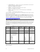
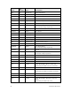
Neuron 6000 Processor
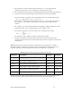
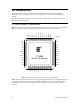
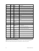
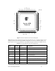
Figure 9 shows the pinout for the Neuron 6000 Processor. The central rectangle in the
figure represents the bottom pad (pin 49), which must be connected to ground.
36 Hardware Resources