
User Manual

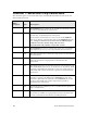

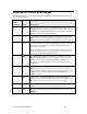


Checklist 2: FT 6000 Smart Transceiver
Connections
This checklist applies to FT 6000 Smart Transceivers.
Check
When
Complete Item Description
FC1 All items in Checklist 1: Series 6000 Chip Connections.
FC2 Environmental and electrical specifications are met, as described
in the FT 6000 Free Topology Smart Transceiver data sheet.
FC3 The FT-X3 Communications Transformer pins are connected as
specified in Transformer Electrical Connections.
FC4 The FT 6000 Smart Transceiver and the FT-X3 Communications
Transformer are placed adjacent to one another on the same PCB.
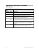
FC5 The connections for the NETP and NETN pins (34 and 32) match
the requirements specified in Connection for an FT 6000 Smart
Transceiver.
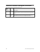
FC6
The CP4 pin (39) is connected to V
DD3
through a 4.99 kΩ pullup
resistor, as shown in Connection for an FT 6000 Smart
Transceiver.
122 Series 6000 Design Checklists