
User Manual


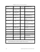
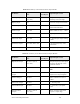
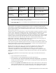

Table 32. Summary of the Timer/Counter Input Models
I/O Model
Applicable I/O
Pins
Total Pins
per Object
Input/Output Value
Dualslope Input IO0, IO1 + (one of
IO4 – IO7)
2 Comparator output of the
dualslope converter logic
Edgelog Input IO4 1 A stream of input transitions
Infrared Input IO4 – IO7 1 Encoded data stream from an
infrared demodulator
Ontime Input IO4 – IO7 1 Pulse width of 0.2 µs – 1.678 s
Period Input IO4 – IO7 1 Signal period of 0.2 µs – 1.678
s
Pulsecount Input IO4 – IO7 1 0 – 65,535 input edges during
0.839 s
Quadrature Input IO4 + IO5, IO6 + IO7 2 ± 16,383 binary Gray code
transitions
Totalcount Input IO4 – IO7 1 0 – 65,535 input edges
Table 33. Summary of the Timer/Counter Output Models
I/O Model
Applicable I/O
Pins
Total Pins
per Object
Input/Output Value
Edgedivide Output IO0, IO1 + (one of
IO4 – IO7)
2 Output frequency is the input
frequency divided by a user-
specified number
Frequency Output IO0, IO1 1 Square wave of 0.3 Hz to 2.5
MHz
Infrared Pattern
Output
IO0, IO1 1 Series of timed repeating
square wave output signals
Oneshot Output IO0, IO1 1 Pulse of duration 0.2 µs to
1.678 s
Pulsecount Output IO0, IO1 1 0 – 65,535 pulses
Pulsewidth Output IO0, IO1 1 0 – 100% duty cycle pulse
train
Stretched Triac
Output
1
IO0, IO1 + (one of
IO4 – IO7)
2 Delay of output pulse with
respect to input edge
Series 6000 Chip Data Book 105