
User Manual


procedures for TP/FT-10 channels, be sure to include the TP/FT-10 system specifications and,
based upon the cable used, the appropriate transmission distance specifications.
Incorporating these specifications can ensure a smoother installation, and provide a resource
for the installer who must troubleshoot the installation.
Note: The following specifications apply to a single network segment. You can combine
multiple segments by using FTT-10A based physical layer repeaters to increase the number
of devices and distance as described in the FTT-10A Free Topology Transceiver User’s Guide.
System Specifications
Each network segment can include up to 64 FT-X3 (or FT X1 or FT-X2) Transformers and FT
Smart Transceivers.
You can use LPT-11 transceivers on network segments with FTT-10A transceivers and FT
Smart Transceivers, but they are subject to additional constraints, particularly on distance.
See the LONWORKS LPT-11 Link Power Transceiver User's Guide for more information.
The average temperature of the wire must not exceed +55°C, although individual segments
of wire may be as hot as +85°C.
As a general rule, the TP/FT-10 channel communication cables should be separated from
high voltage power cables. Follow local electrical codes with regard to cable placement.
Transmission Distance Specifications
Table 27 and Table 28 list the transmission distance specifications for the supported cable
types.
Table 27. Doubly Terminated Bus Topology Specifications
Cable Type Maximum Bus Length (Meters)
Belden 85102 2700
Belden 8471 2700
NEMA Type 4, 22 AWG 1400
J-Y(ST)Y 2x2x0.8 900
ANSI/TIA/EIA Category 5 or 6 900
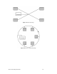
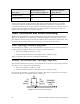
A doubly-terminated bus can have stubs of up to 3 meters from the bus to each device.
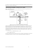
Table 28. Free Topology Specifications
Cable Type
Maximum Device-to-
Device Distance (Meters)
Maximum Total Wire
Length (Meters)
Belden 85102 500 500
Belden 8471 400 500
NEMA Type 4, 22 AWG 400 500
Series 6000 Chip Data Book 95