LONWORKS ® PCLTA-21 PCI Interface User’s Guide Version 1 Corporation 078-0271-01A
Echelon, LON, LONWORKS, LonTalk, LonBuilder, NodeBuilder, LONMARK, Neuron, i.LON, LonManager, 3120, and 3150 are trademarks of Echelon Corporation registered in the United States and other countries. LonMaker is a trademark of Echelon Corporation. Other brand and product names are trademarks or registered trademarks of their respective holders.
FCC NOTICE (for USA only) Federal Communications Commission Radio Frequency Interference Statement Warning: This equipment has been tested and found to comply with the limits for a Class B digital device, pursuant to part 15 of the FCC Rules. These limits are designed to provide reasonable protection against harmful interference in a residential installation.
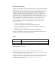
Contents FCC Notice CE Declaration of Conformance 1 PCLTA-21 Introduction Overview Audience Content Related Documentation 1 2 2 2 2 2 Installing the PCLTA-21 Card PCLTA-21 Card Software Installation Windows® 2000 and XP Software Installation Procedure Windows 98 Software Installation Procedure Windows 2000 and XP Software Removal Procedure Windows 98 Software Removal Procedure Windows 2000 and XP Virtual-Mode DOS Driver Installation Results Windows 98 Virtual-Mode DOS Driver Installation Results PCLTA-
4 iv Automatic Flush Cancel Transceiver Diagnostics General Settings Uplink Buffering PCLTA-21 Diagnostics Driver Status Diagnostic Commands Test Comm Service Restart Reset 18 18 19 19 19 20 20 21 21 22 23 23 23 Electrical and Mechanical Interfaces PCLTA-21 Board Layout PCLTA-21 TP-RS485 Jumper Settings P1 and P2 PCI Bus Connector Network Connector Mechanical Considerations 25 26 27 27 27 28 Echelon
1 PCLTA-21 Introduction This guide describes the mechanical characteristics and the hardware and software driver installation for the Echelon PCLTA21 Interface (Models 74501, 74502, 74503, 74504, and 74505). ® Echelon’s PCLTA-21 card is a high-performance LONWORKS interface for desktop and embedded personal computers equipped with a 3 or 5V 32-bit PCI interface and a compatible operating system.
Overview The PCLTA-21 card provides any PC equipped with a 32-bit PCI interface and compatible Windows operating system access to a LONWORKS network. The PCLTA-21 installation software provides a software-based control panel and a software driver for Microsoft Windows 98, 2000, or XP operating system. Installation software also is available on Echelon’s web site at www.echelon.com/downloads.
2 Installing the PCLTA-21 Card This chapter describes the procedures for installing the PCLTA-21 card.
PCLTA-21 Card Software Installation There are two versions of the PCLTA-21 installation software, one for Windows 2000 and XP and one for Windows 98. Each version installs the files required by the associated Windows operating system to recognize the PCLTA-21 card, as well as the downloadable LNS and MIP images. Windows 2000 and XP Software Installation Procedure To install the PCLTA-21 software on a Windows 2000 or XP PC, follow the instructions below.
! The path may be modified using the Browse button; however, if a directory other than c:\lonworks is chosen, the PCLTA-21 images path will have to be specified to enable use of the PCLTA-21 card. This is accomplished during PCLTA-21 Configuration. See Chapter 3, Configuring and Testing the PCLTA-21 Adapter. 7. There is a limit of six (6) PCLTA-21 cards in a single PC. 8.
3. Open the Windows Start menu and select the Run command. 4. When prompted for a program name, enter the following: E:Win98\SETUP.EXE (where E: represents your CD ROM) 5. When prompted with a list of languages, click on the desired language. A checkmark will appear to the left of the language to be installed. 6. When prompted for a destination directory, enter the desired installation directory.
DOS applications to be used in a Windows 98 DOS shell/window. For more information see Virtual-Mode DOS Driver later in this chapter. The following line is added to the CONFIG.SYS file: DEVICE=C:\LONWORKS\BIN\LDVVDD.SYS /D1 10. Software installation is complete. At the prompt to restart the computer, remove the PCLTA-21 installation CD and shut down the computer. Next insert the PCLTA-21 into a PCI slot and turn the computer back on. Windows will discover and recognize the PCLTA-21.
Windows 2000 and XP Virtual-Mode DOS Driver Installation Results The Windows 2000 and XP PCLTA-21 installation software will prompt the installer to automatically add the virtual-mode DOS driver. This driver is small in size, and allows a DOS session under Windows to have access to the PCLTA-21 card through the device driver running as a part of Windows. The driver will not function unless a Windows session is running and the PCLTA-21 device driver is installed.
parameter you would access the 9th device, as determined by the /D9 option. These options are typically needed when more than one LONWORKS network interface is present in the system. PCLTA-21 Card Hardware Installation ! ESD Warning This product contains devices which are sensitive to static electricity. Before installing or removing the PCLTA-21 card or the network cables, discharge any static electricity which may have accumulated to earth ground by touching the case or power supply. 1.
Troubleshooting As a plug-and-play device, the PCLTA-21 card should operate as desired following completion of the installation process. If the card does not function correctly, the most likely causes are system resource constraints or software incompatibilities. These problems are described in detail in the following sections. Installing the PCLTA-21 Card before Software Installation The following section applies to Windows 98 only.
The PCLTA-21 LONWORKS Network Interface device icon is found under the LONWORKS Interface device type. If there is a problem with the card, there will be a red circle with an exclamation point next to its icon. IRQ resource problems may generally be resolved by disabling another device in the system. More information can be found in the Hardware Conflict troubleshooting portion of the Windows 98 on-line Help file. Access the hardware conflict troubleshooter through the procedure outlined below: 1.
Common Resource Problems under Windows 98 The following situations produce an additional drain on system resources that may be hard to manage. Conflicts arising from these situations can generally be resolved by selectively disabling devices to free up the required resources.
The following example creates a device alias that routes all service requests for LON1 to the PCCLON1 PCLTA-21 card. [DRIVERALIAS] LON1=PCCLON1 LonManager ISA Protocol Analyzer Compatibility The device driver for the PCLTA-21 card and the driver for the Model 33100-00 LonManager Protocol Analyzer ISA-bus card share the same Windows VxD identifier. As a result, both types of cards cannot run on a PC at the same time. So, the PCLTA-21 installation software will comment out the SYSTEM.
3 Configuring and Testing the PCLTA-21 Card This chapter explains how to configure and test the PCLTA-21 card using the Control Panel application installed in Chapter 2.
PCLTA-21 Configuration PCLTA-21 configuration is accomplished by using the LONWORKS Plug ‘n Play control panel application. Open the control panel application by selecting the LONWORKS ® Plug ‘n Play icon in the Windows Control Panel. Figure 3.1 PCLTA-21 Control Panel and Icon The LONWORKS Plug ‘n Play control panel application is divided into three parts: a device selection area, a general settings area, and a control section.
To manually initialize the PCLTA-21 card, verify that the control panel application’s System Image Path entry is correct, then click the Apply button. An error will be reported if an attempt is made to view the transceiver type before the PCLTA-21 card is initialized. Testing the card with the Diagnostics button produces the diagnosis: “Image file not found.” In this case, return to the control panel application’s main window and manually initialize the PCLTA-21 card.
Network Image Windows XP or 2000 Windows 98 LNS Fast Network Image (LNS 3 and newer) PCLTA21VNI PCL10VNI TX LED lights every time the PCLTA-21 sends a packet. RX LED lights every time the PCLTA-21 sees a packet, whether or not it is addressed to the PCLTA-21. LNS Network Image Interface (LNS 1 and 2) PCLTA21NSI Basic Network Interface Application (MIP and older API Applications) PCLTA21L7 NSIPCLTA TX and RX LEDs do not function with this image.
Figure 3.3 PCLTA-21 Transceiver Dialog Box Diagnostics Opens the PCLTA-21 Diagnostics dialog. For more information, see the section on PCLTA-21 Diagnostics, later in this chapter. General Settings The PCLTA-21-generic options consist of four controls (figure 3.4). These controls are defined as follows: Figure 3.4 PCLTA-21 Generic Controls Uplink Buffering For Windows 2000 and XP, this controls the number of 4Kbyte operating system pages that are allocated for message buffering within the driver.
For Windows 98, the term “Layer6 Buffering” refers to the same parameter as Uplink Buffering. There is also a “Layer2 Buffering” setting that should always be left at its default value of 20. PCLTA-21 Diagnostics A number of diagnostic and testing services are provided by the PCLTA-21 control panel application. Clicking the Diagnostics button in the main control panel window displays the PCLTA-21 Diagnostics dialog.
• Loaded Image Size: the size, in bytes, of the currently-loaded PCLTA-21 system image. This may be zero if the PCLTA-21 card is in the initial boot state. • Interrupt Count: the number of interrupts the driver has processed for this device. This value is set to zero when the device is physically reset. Diagnostic Commands The diagnostic commands are invoked by clicking one of the buttons displayed in figure 3.6.
Comm ! The Comm button is not available if you are using the PCLTA21VNI image. If you are using the PCLTA21VNI image, first select the PCLTA21NSI image, click Apply, run the Comm test, then reselect the PCLTA21VNI image, and click Apply. The Comm feature is not designed to work across routers. The Comm button verifies communications between the PCLTA-21 card and another device on the network.
Service ! The Service button is not available if you are using the PCLTA21VNI image. If you are using the PCLTA21VNI image, first select the PCLTA21NSI image, click Apply, click the Service button, then reselect the PCLTA21VNI image, and click Apply. The Service button will cause the PCLTA-21 card to broadcast a service pin message on the network. The service pin message will not be sent if the card is in the post-reset flush state (see Automatic Flush Cancel).
24 Configuring and Testing the PCLTA-21 Card
4 Electrical and Mechanical Interfaces This chapter describes the hardware interfaces and mechanical layout of the PCLTA-21 card.
PCLTA-21 Board Layout Figure 4.1 shows the layout of the PCLTA-21 card Models 74501, 74502, 74503, and 74504. Model 74504 (TP-RS485) includes jumpers that must be configured to set the correct speed on the RS-485 channel (figure 4.2). Figure 4.
JP1 JP1 ID4 ID4 RS485 XID RS485 XID ID3 ID3 ID2 ID2 ID1 ID1 ID0 ID0 TP/RS485-78 ID = 12 TP/RS485-39 ID = 5 (default) JP1 JP1 ID4 ID4 RS485 XID RS485 XID ID3 ID2 ID1 ID0 ID3 ID2 ID1 ID0 TP/RS485-625 ID = 10 TP/RS485-1250 ID = 11 Figure 4.2 PCLTA-21 TP-RS485 Jumper Settings P1 and P2 PCI Bus Connector The pinout of the PCI connector is the standard pinout for the 32-bit PCI bus used in Windows-compatible PCs. The power drawn from the host is 250mA @ 5VDC, typical.
Terminal Connection 3 Shield 2 RS-485 - 1 RS-485+ ! Use only shielded cabling suitable for an RS-485 channel. The use of unshielded cabling could result in damage to the adapter due to common mode voltage associated with differences in ground potential between different devices. Mechanical Considerations PCLTA-21 Models 74401 – 74404 measure 2.54” (6.5cm) H x 4.72” (12cm) L. All models are equipped with a full-height chassis bracket and a low profile bracket.