
System information


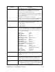


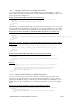

Table Of Contents
- Table of Contents
- 1 Introduction to the SmartServer SOAP/XML Interface
- 2 SOAP Messages and the SmartServer WSDL File
- 2.1 SmartServer Naming Structure
- 2.2 SmartServer WSDL File
- 2.3 Security
- 2.4 SOAP Request and Response Message Structure
- 2.5 SOAP Messages Formats
- 2.6 Data Point References
- 2.7 UCPTcurrentConfig
- 2.8 Fault Structure
- 2.9 LonString type
- 2.10 SOAP Message Examples
- 3 SmartServer Applications and the SOAP/XML Interface
- 3.1 Overview of SmartServer Applications
- 3.2 SmartServer XML Configuration Files
- 3.3 SmartServer Resource Files
- 3.3.1 Standard Network Variable Type (SNVT) Device Resource Files
- 3.3.2 Standard Configuration Property Type (SCPT) Device Resource Files
- 3.3.3 User Defined Network Variable Type (UNVT) Device Resource Files
- 3.3.4 User Defined Configuration Property Type (UCPT) Device Resource Files
- 3.3.5 Data Point Templates
- 3.3.6 Data Formatting
- 3.4 SOAP Functions
- 3.5 Performance Issues
- 4 Using the SmartServer Data Server
- 4.1 Creating and Modifying the Data Point XML Files
- 4.2 Overview of the Data Point XML File
- 4.3 Data Server SOAP Interface
- 4.3.1 Using the List Function on the Data Server
- 4.3.2 Using the Get Function on the Data Server
- 4.3.3 Using the Set Function on the Data Server
- 4.3.4 Using the Read Function on the Data Server
- 4.3.5 Using the Write Function on the Data Server
- 4.3.6 Using the Invoke Function to Reset Data Point Priorities
- 4.3.7 Data Point Values and Priority Levels
- 4.3.8 Using the Delete Function on the Data Server
- 4.4 Using the Web Binder Application
- 5 Data Loggers
- 5.1 Overview of the Data Logger XML File
- 5.2 Creating and Modifying the Data Logger XML File
- 5.3 Data Logger SOAP Interface
- 6 Alarm Generator
- 6.1 Overview of the Alarm Generator XML File
- 6.2 Creating and Modifying the Alarm Generator XML File
- 6.3 Alarm Generator SOAP Interface
- 7 Alarm Notifier
- 7.1 Overview of the AlarmNotifier XML File
- 7.2 Creating and Modifying the Alarm Notifier XML File
- 7.3 Alarm Notifier SOAP Interface
- 7.3.1 Using the List Function on an Alarm Notifier
- 7.3.2 Using the Get Function on an Alarm Notifier
- 7.3.3 Using the Set Function on an Alarm Notifier
- 7.3.4 Using the Read Function on an Alarm Notifier
- 7.3.5 Using the Write Function on an Alarm Notifier Log File
- 7.3.6 Using the Clear Function on an Alarm Notifier Log File
- 7.3.7 Using the Delete Function on an Alarm Notifier
- 8 Analog Function Block
- 9 Scheduler
- 9.1 Overview of the Scheduler XML File
- 9.2 Creating and Modifying the Scheduler XML File
- 9.3 Scheduler SOAP Interface
- 10 Calendar
- 10.1 Overview of the Calendar XML File
- 10.2 Creating and Modifying the Calendar XML File
- 10.3 Calendar SOAP Interface
- 11 Real Time Clock
- 12 Type Translator
- 12.1 Overview of the Type Translator XML File
- 12.2 Creating and Modifying the Type Translator XML File
- 12.3 Type Translator SOAP Interface
- 12.3.1 Using the List Function on a Type Translator
- 12.3.2 Using the Get Function on a Type Translator
- 12.3.3 Using the Set Function on a Type Translator
- 12.3.4 Pre Defined Type Translator Rules
- 12.3.4.1 16xSNVT_switch_TO_SNVT_state
- 12.3.4.2 SNVT_lev_disc_TO_SNVT_occupancy
- 12.3.4.3 SNVT_lev_disc_TO_SNVT_switch
- 12.3.4.4 SNVT_occupancy_TO_SNVT_setting
- 12.3.4.5 SNVT_scene_TO_SNVT_setting
- 12.3.4.6 SNVT_scene_TO_SNVT_switch
- 12.3.4.7 SNVT_setting_TO_SNVT_switch
- 12.3.4.8 SNVT_state_TO_16xSNVT_switch
- 12.3.4.9 SNVT_switch_TO_SNVT_lev_disc
- 13 Type Translator Rules
- 14 LonWorks Driver
- 14.1 LonWorks Networks
- 14.2 LonWorks Channels
- 14.3 LonWorks Devices
- 14.4 Routers
- 14.5 Remote Network Interface
- 14.6 LonWorks Functional Blocks
- 14.7 Network Variables (LonWorks Data Points)
- 14.8 Configuration Properties (LonWorks Data Points)
- 14.9 LonWorks Connections
- 15 Modbus Driver
- 16 M Bus Driver
- 17 Virtual Driver
- 18 File System Data
- 19 System Information Methods
- 20 Using the SOAP Interface as a Web Service
- 21 Programming Examples
- 21.1 Visual C#.NET Examples
- 21.1.1 Reading and Writing Data Point Values in Visual C# .NET
- 21.1.2 Creating and Reading a Data Logger in Visual C# .NET
- 21.1.3 Creating a Scheduler and Calendar in Visual C# .NET
- 21.1.4 Creating and Installing a LonWorks Device in Visual C# .NET
- 21.1.5 Commissioning External Devices in Visual C# .NET
- 21.1.6 Discovering and Installing External Devices in Visual C# .NET
- 21.1.7 Configuring the SmartServer in Visual C# .NET
- 21.2 Visual Basic.NET Examples
- 21.2.1 Reading and Writing Data Point Values in Visual Basic.NET
- 21.2.2 Creating and Reading a Data Logger in Visual Basic. NET
- 21.2.3 Creating a Scheduler and Calendar in Visual Basic.NET
- 21.2.4 Creating and Installing a LonWorks Device in Visual Basic.NET
- 21.2.5 Commissioning External Devices in Visual Basic.NET
- 21.2.6 Discovering and Installing External Devices in Visual Basic.NET
- 21.2.7 Configuring the SmartServer in Visual Basic.NET
- 21.1 Visual C#.NET Examples
- 22 Programming the SmartServer with Java
- Appendix A: SOAP Tester Example

i.LON SmartServer 2.0 Programmer’s Reference
16-10
Property Description
(AT_SECONDARY) addressing. Primary addressing is
preferred because it makes replacing M-Bus devices more
transparent. Each of these addressing methods is described
as follows:
Primary. The primary address is assigned by the
network management tool used to install the M-Bus
device (analogous to a L
ONWORKS subnet/icon
address).
Secondary. The secondary address is burned into the
device at the factory (analogous to a L
ONWORKS
Neuron ID).
• <UCPTmbusPrimaryAddress>. The primary address must
be between 0 to 250.
• <UCPTmbusSecondaryAddress>. The secondary address
must be between 0 to 99,999,999.
16.2.3
Using the Set Function on M-Bus Devices
You can use the Set function to overwrite the configuration of an M-Bus device, or to create a new
M-Bus device. The input parameters you supply to the function will include one or more <Item>
elements. Each <Item> element includes a <UCPTname> property that specifies a unique M-Bus
device to be created or modified.
Each <Item> element may also include a series of properties that define the configuration of the new
(or modified) M-Bus device. This set of properties is the same whether you are creating a new M-Bus
device or modifying an existing M-Bus device.
• If you are modifying an existing M-Bus device, you must specify the <UCPThandle> property. In
addition, all other properties should be filled; otherwise the values stored in them are erased. The
previous section,
Using the Get Function on M-Bus Devices, details the properties you can include
in the Set function.
You can set multiple M-Bus devices with a single Set message. However, you should not attempt to
create or write to more than 100 M-Bus devices with a single call to the Set function. The following
example demonstrates how to create a new M-Bus device.
Request (create a new M-Bus device on the SmartServer)
<Set xmlns="http://wsdl.echelon.com/web_services_ns/ilon100/v4.0/message/">
<iLonItem>
<Item xsi:type="MBS_Device_Cfg">
<UCPTname>Net/M-Bus Channel/M-Bus Device 2</UCPTname>
</Item>
</iLonItem
</Set>
Response
<SetResponse xmlns="http://wsdl.echelon.com/web_services_ns/ilon100/v4.0/message/">
<iLonItem>
<UCPTfaultCount>0</UCPTfaultCount>
<Item>
<UCPTname>Net/M-Bus Channel/M-Bus Device 2</UCPTname>
</Item>
</iLonItem>
</SetResponse>