
System information


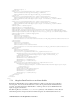
Table Of Contents
- Table of Contents
- 1 Introduction to the SmartServer SOAP/XML Interface
- 2 SOAP Messages and the SmartServer WSDL File
- 2.1 SmartServer Naming Structure
- 2.2 SmartServer WSDL File
- 2.3 Security
- 2.4 SOAP Request and Response Message Structure
- 2.5 SOAP Messages Formats
- 2.6 Data Point References
- 2.7 UCPTcurrentConfig
- 2.8 Fault Structure
- 2.9 LonString type
- 2.10 SOAP Message Examples
- 3 SmartServer Applications and the SOAP/XML Interface
- 3.1 Overview of SmartServer Applications
- 3.2 SmartServer XML Configuration Files
- 3.3 SmartServer Resource Files
- 3.3.1 Standard Network Variable Type (SNVT) Device Resource Files
- 3.3.2 Standard Configuration Property Type (SCPT) Device Resource Files
- 3.3.3 User Defined Network Variable Type (UNVT) Device Resource Files
- 3.3.4 User Defined Configuration Property Type (UCPT) Device Resource Files
- 3.3.5 Data Point Templates
- 3.3.6 Data Formatting
- 3.4 SOAP Functions
- 3.5 Performance Issues
- 4 Using the SmartServer Data Server
- 4.1 Creating and Modifying the Data Point XML Files
- 4.2 Overview of the Data Point XML File
- 4.3 Data Server SOAP Interface
- 4.3.1 Using the List Function on the Data Server
- 4.3.2 Using the Get Function on the Data Server
- 4.3.3 Using the Set Function on the Data Server
- 4.3.4 Using the Read Function on the Data Server
- 4.3.5 Using the Write Function on the Data Server
- 4.3.6 Using the Invoke Function to Reset Data Point Priorities
- 4.3.7 Data Point Values and Priority Levels
- 4.3.8 Using the Delete Function on the Data Server
- 4.4 Using the Web Binder Application
- 5 Data Loggers
- 5.1 Overview of the Data Logger XML File
- 5.2 Creating and Modifying the Data Logger XML File
- 5.3 Data Logger SOAP Interface
- 6 Alarm Generator
- 6.1 Overview of the Alarm Generator XML File
- 6.2 Creating and Modifying the Alarm Generator XML File
- 6.3 Alarm Generator SOAP Interface
- 7 Alarm Notifier
- 7.1 Overview of the AlarmNotifier XML File
- 7.2 Creating and Modifying the Alarm Notifier XML File
- 7.3 Alarm Notifier SOAP Interface
- 7.3.1 Using the List Function on an Alarm Notifier
- 7.3.2 Using the Get Function on an Alarm Notifier
- 7.3.3 Using the Set Function on an Alarm Notifier
- 7.3.4 Using the Read Function on an Alarm Notifier
- 7.3.5 Using the Write Function on an Alarm Notifier Log File
- 7.3.6 Using the Clear Function on an Alarm Notifier Log File
- 7.3.7 Using the Delete Function on an Alarm Notifier
- 8 Analog Function Block
- 9 Scheduler
- 9.1 Overview of the Scheduler XML File
- 9.2 Creating and Modifying the Scheduler XML File
- 9.3 Scheduler SOAP Interface
- 10 Calendar
- 10.1 Overview of the Calendar XML File
- 10.2 Creating and Modifying the Calendar XML File
- 10.3 Calendar SOAP Interface
- 11 Real Time Clock
- 12 Type Translator
- 12.1 Overview of the Type Translator XML File
- 12.2 Creating and Modifying the Type Translator XML File
- 12.3 Type Translator SOAP Interface
- 12.3.1 Using the List Function on a Type Translator
- 12.3.2 Using the Get Function on a Type Translator
- 12.3.3 Using the Set Function on a Type Translator
- 12.3.4 Pre Defined Type Translator Rules
- 12.3.4.1 16xSNVT_switch_TO_SNVT_state
- 12.3.4.2 SNVT_lev_disc_TO_SNVT_occupancy
- 12.3.4.3 SNVT_lev_disc_TO_SNVT_switch
- 12.3.4.4 SNVT_occupancy_TO_SNVT_setting
- 12.3.4.5 SNVT_scene_TO_SNVT_setting
- 12.3.4.6 SNVT_scene_TO_SNVT_switch
- 12.3.4.7 SNVT_setting_TO_SNVT_switch
- 12.3.4.8 SNVT_state_TO_16xSNVT_switch
- 12.3.4.9 SNVT_switch_TO_SNVT_lev_disc
- 13 Type Translator Rules
- 14 LonWorks Driver
- 14.1 LonWorks Networks
- 14.2 LonWorks Channels
- 14.3 LonWorks Devices
- 14.4 Routers
- 14.5 Remote Network Interface
- 14.6 LonWorks Functional Blocks
- 14.7 Network Variables (LonWorks Data Points)
- 14.8 Configuration Properties (LonWorks Data Points)
- 14.9 LonWorks Connections
- 15 Modbus Driver
- 16 M Bus Driver
- 17 Virtual Driver
- 18 File System Data
- 19 System Information Methods
- 20 Using the SOAP Interface as a Web Service
- 21 Programming Examples
- 21.1 Visual C#.NET Examples
- 21.1.1 Reading and Writing Data Point Values in Visual C# .NET
- 21.1.2 Creating and Reading a Data Logger in Visual C# .NET
- 21.1.3 Creating a Scheduler and Calendar in Visual C# .NET
- 21.1.4 Creating and Installing a LonWorks Device in Visual C# .NET
- 21.1.5 Commissioning External Devices in Visual C# .NET
- 21.1.6 Discovering and Installing External Devices in Visual C# .NET
- 21.1.7 Configuring the SmartServer in Visual C# .NET
- 21.2 Visual Basic.NET Examples
- 21.2.1 Reading and Writing Data Point Values in Visual Basic.NET
- 21.2.2 Creating and Reading a Data Logger in Visual Basic. NET
- 21.2.3 Creating a Scheduler and Calendar in Visual Basic.NET
- 21.2.4 Creating and Installing a LonWorks Device in Visual Basic.NET
- 21.2.5 Commissioning External Devices in Visual Basic.NET
- 21.2.6 Discovering and Installing External Devices in Visual Basic.NET
- 21.2.7 Configuring the SmartServer in Visual Basic.NET
- 21.1 Visual C#.NET Examples
- 22 Programming the SmartServer with Java
- Appendix A: SOAP Tester Example
i.LON SmartServer 2.0 Programmer’s Reference
7-16
<UCPTdataPointPath>DataPoint[@dpType=“Output” and UCPTnickName=“Net/LON/iLON App/Data
Logger[0]/nviDlClear[0]”]</UCPTdataPointPath>
<UCPTpointValue>ON</UCPTpointValue>
<UCPTminLevel>255</UCPTminLevel>
<UCPTmaxLevel>0</UCPTmaxLevel>
<UCPTnackDelay>0</UCPTnackDelay>
</ActiveDest>
<PassiveDest>
<UCPTminLevel>255</UCPTminLevel>
<UCPTmaxLevel>0</UCPTmaxLevel>
<UCPTnackDelay>0</UCPTnackDelay>
</PassiveDest>
</AlarmDest>
You can optionally fill in the <UCPTdestEnable> property for each <AlarmDest> element. You can
reference a SNVT_switch data point by its <UCPTpointName> with this property. The <AlarmDest>
will be enabled if that data point is set to 100.0 1, or disabled if that data point is set to 0.0 0. You can
set this data point with a L
ONWORKS switch or with the Scheduler application. In this fashion, you can
enable or disable destination sets as you like.
Every <AlarmDest> should contain zero or one <ActiveDest> and zero or one <PassiveDest>
elements. The following table describes the properties you must define for each <ActiveDest> and
<PassiveDest> element. Each <ActiveDest> element defines an active destination for the Alarm
Notifier. Each <PassiveDest> element defines a passive destination for the alarm notifier.
The active destinations for an Alarm Notifier are used when the input data point is updated, and meets
the conditions defined by any of the Alarm Notifier’s active conditions. The passive destinations for
an Alarm Notifier are used when the input data point is updated, and meets any of the conditions
defined by the Alarm Notifier’s passive conditions.
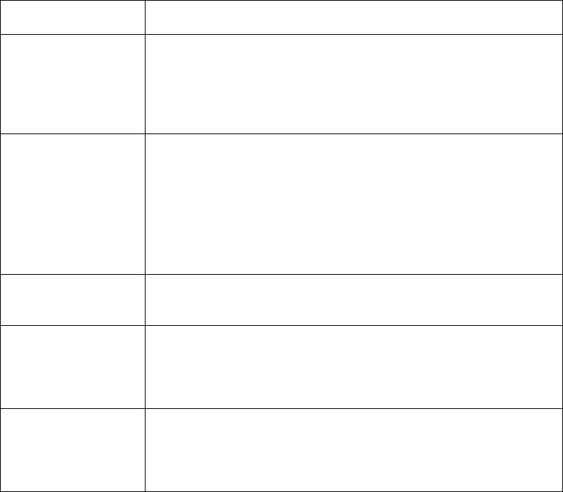
Property Description
<UCPTmailPath>
Contains an e-mail nickname, as defined for an e-mail profile created
for the Alarm Notifier. This signifies the e-mail profile to be used
each time an alarm notification uses this destination. The string must
be a valid xPath expression that points to an e-mail profile. The
e-mail will be sent after <UCPTnackDelay> expired.
<UCPTdataPointPath>
Contains the xPath to the <DataPoint> with dpType=”Output” that
will be updated when the active destination is used, and the e-mail for
the alarm notification has been sent.
If you want to create a destination that will automatically update the
data point during an alarm notification without waiting for the e-mail
to be sent, do not fill in the <UCPTnackDelay> property. This is only
applicable if the alarm has not been acknowledged.
<UCPTpointValue>
The value or preset to be written to the output data point specified by
<UCPTdataPointPath>.
<UCPTminLevel>
The minimum alarm level required for this destination to be used.
The alarm level for an alarm notification is determined by the value
assigned to the <UCPTlevel> property for of condition set that caused
it.
<UCPTmaxLevel>
The maximum alarm level required for this destination to be used.
The alarm level for an alarm notification is determined by the value
assigned to the <UCPTlevel> property of the condition set that caused
the alarm.