
System information
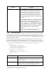


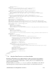
Table Of Contents
- Table of Contents
- 1 Introduction to the SmartServer SOAP/XML Interface
- 2 SOAP Messages and the SmartServer WSDL File
- 2.1 SmartServer Naming Structure
- 2.2 SmartServer WSDL File
- 2.3 Security
- 2.4 SOAP Request and Response Message Structure
- 2.5 SOAP Messages Formats
- 2.6 Data Point References
- 2.7 UCPTcurrentConfig
- 2.8 Fault Structure
- 2.9 LonString type
- 2.10 SOAP Message Examples
- 3 SmartServer Applications and the SOAP/XML Interface
- 3.1 Overview of SmartServer Applications
- 3.2 SmartServer XML Configuration Files
- 3.3 SmartServer Resource Files
- 3.3.1 Standard Network Variable Type (SNVT) Device Resource Files
- 3.3.2 Standard Configuration Property Type (SCPT) Device Resource Files
- 3.3.3 User Defined Network Variable Type (UNVT) Device Resource Files
- 3.3.4 User Defined Configuration Property Type (UCPT) Device Resource Files
- 3.3.5 Data Point Templates
- 3.3.6 Data Formatting
- 3.4 SOAP Functions
- 3.5 Performance Issues
- 4 Using the SmartServer Data Server
- 4.1 Creating and Modifying the Data Point XML Files
- 4.2 Overview of the Data Point XML File
- 4.3 Data Server SOAP Interface
- 4.3.1 Using the List Function on the Data Server
- 4.3.2 Using the Get Function on the Data Server
- 4.3.3 Using the Set Function on the Data Server
- 4.3.4 Using the Read Function on the Data Server
- 4.3.5 Using the Write Function on the Data Server
- 4.3.6 Using the Invoke Function to Reset Data Point Priorities
- 4.3.7 Data Point Values and Priority Levels
- 4.3.8 Using the Delete Function on the Data Server
- 4.4 Using the Web Binder Application
- 5 Data Loggers
- 5.1 Overview of the Data Logger XML File
- 5.2 Creating and Modifying the Data Logger XML File
- 5.3 Data Logger SOAP Interface
- 6 Alarm Generator
- 6.1 Overview of the Alarm Generator XML File
- 6.2 Creating and Modifying the Alarm Generator XML File
- 6.3 Alarm Generator SOAP Interface
- 7 Alarm Notifier
- 7.1 Overview of the AlarmNotifier XML File
- 7.2 Creating and Modifying the Alarm Notifier XML File
- 7.3 Alarm Notifier SOAP Interface
- 7.3.1 Using the List Function on an Alarm Notifier
- 7.3.2 Using the Get Function on an Alarm Notifier
- 7.3.3 Using the Set Function on an Alarm Notifier
- 7.3.4 Using the Read Function on an Alarm Notifier
- 7.3.5 Using the Write Function on an Alarm Notifier Log File
- 7.3.6 Using the Clear Function on an Alarm Notifier Log File
- 7.3.7 Using the Delete Function on an Alarm Notifier
- 8 Analog Function Block
- 9 Scheduler
- 9.1 Overview of the Scheduler XML File
- 9.2 Creating and Modifying the Scheduler XML File
- 9.3 Scheduler SOAP Interface
- 10 Calendar
- 10.1 Overview of the Calendar XML File
- 10.2 Creating and Modifying the Calendar XML File
- 10.3 Calendar SOAP Interface
- 11 Real Time Clock
- 12 Type Translator
- 12.1 Overview of the Type Translator XML File
- 12.2 Creating and Modifying the Type Translator XML File
- 12.3 Type Translator SOAP Interface
- 12.3.1 Using the List Function on a Type Translator
- 12.3.2 Using the Get Function on a Type Translator
- 12.3.3 Using the Set Function on a Type Translator
- 12.3.4 Pre Defined Type Translator Rules
- 12.3.4.1 16xSNVT_switch_TO_SNVT_state
- 12.3.4.2 SNVT_lev_disc_TO_SNVT_occupancy
- 12.3.4.3 SNVT_lev_disc_TO_SNVT_switch
- 12.3.4.4 SNVT_occupancy_TO_SNVT_setting
- 12.3.4.5 SNVT_scene_TO_SNVT_setting
- 12.3.4.6 SNVT_scene_TO_SNVT_switch
- 12.3.4.7 SNVT_setting_TO_SNVT_switch
- 12.3.4.8 SNVT_state_TO_16xSNVT_switch
- 12.3.4.9 SNVT_switch_TO_SNVT_lev_disc
- 13 Type Translator Rules
- 14 LonWorks Driver
- 14.1 LonWorks Networks
- 14.2 LonWorks Channels
- 14.3 LonWorks Devices
- 14.4 Routers
- 14.5 Remote Network Interface
- 14.6 LonWorks Functional Blocks
- 14.7 Network Variables (LonWorks Data Points)
- 14.8 Configuration Properties (LonWorks Data Points)
- 14.9 LonWorks Connections
- 15 Modbus Driver
- 16 M Bus Driver
- 17 Virtual Driver
- 18 File System Data
- 19 System Information Methods
- 20 Using the SOAP Interface as a Web Service
- 21 Programming Examples
- 21.1 Visual C#.NET Examples
- 21.1.1 Reading and Writing Data Point Values in Visual C# .NET
- 21.1.2 Creating and Reading a Data Logger in Visual C# .NET
- 21.1.3 Creating a Scheduler and Calendar in Visual C# .NET
- 21.1.4 Creating and Installing a LonWorks Device in Visual C# .NET
- 21.1.5 Commissioning External Devices in Visual C# .NET
- 21.1.6 Discovering and Installing External Devices in Visual C# .NET
- 21.1.7 Configuring the SmartServer in Visual C# .NET
- 21.2 Visual Basic.NET Examples
- 21.2.1 Reading and Writing Data Point Values in Visual Basic.NET
- 21.2.2 Creating and Reading a Data Logger in Visual Basic. NET
- 21.2.3 Creating a Scheduler and Calendar in Visual Basic.NET
- 21.2.4 Creating and Installing a LonWorks Device in Visual Basic.NET
- 21.2.5 Commissioning External Devices in Visual Basic.NET
- 21.2.6 Discovering and Installing External Devices in Visual Basic.NET
- 21.2.7 Configuring the SmartServer in Visual Basic.NET
- 21.1 Visual C#.NET Examples
- 22 Programming the SmartServer with Java
- Appendix A: SOAP Tester Example

i.LON SmartServer 2.0 Programmer’s Reference
7-9
Property Description
<AlarmDest>
Each <AlarmDest> element defines a group of active and
passive alarm destinations the Alarm Notifier will use. The
active destinations are signified by a list of <ActiveDest>
child elements within the <AlarmDest> element. The
passive destinations are signified by a list of <PassiveDest>
child elements within the <AlarmDest> element. For a
description of the properties that must be defined within
each of these child elements, see
Active and Passive Alarm
Destinations.
Each <AlarmDest> element also contains 2 global elements:
its index number (UCPTindex), and its enable data point
(UCPTenablePath). The <UCPTenablePath> property is
optional. You can reference a SNVT_switch data point by
its name (UCPTname) here. The <AlarmDest> will then be
enabled when that data point is set to 100.0 1, or disabled if
that data point is set to 0.0 0. You could set this data point
with a L
ONWORKS switch, or with the Scheduler
application.
This allows you to enable or disable an Alarm Notifier’s
destination sets under different circumstances.
7.3.2.1 Input Data Points
The following table describes the properties that you must define within each <DataPoint> element.
As described in the previous section, each <DataPoint> element defines an input data point for the
Alarm Notifier. The input data points have an xsi type attribute of “UFPTalarmNotifier_Input_DpRef”
and a dpType attribute of “Input”.
Each time an input data point is updated, the Alarm Notifier will check if it has reached an alarm
condition. If an input data point is updated and meets an active or passive alarm condition, then an
alarm notification will be logged, and the applicable passive or active alarm destinations will be used.
<DataPoint xsi:type="UFPTalarmNotifier_Input_DpRef" dpType="Input" discrim="dir_in" >
<UCPTname>Net/LON/iLON App/Data Logger[0]/nvoDlLevAlarm[0]</UCPTname>
<AlarmFlags>
<UCPTlogEnable>1</UCPTlogEnable>
<UCPTinvisible>0</UCPTinvisible>
<UCPTclearRequired>0</UCPTclearRequired>
<UCPTackRequired>1</UCPTackRequired>
<UCPTdisabled>0</UCPTdisabled>
<UCPTcovEnabled>1</UCPTcovEnabled>
</AlarmFlags>
<UCPTalarmGroup>0</UCPTalarmGroup>
<UCPTalarmPriority2>0</UCPTalarmPriority2>
<UCPTdescription/>
</DataPoint>
Property Description
<UCPTname>
The name of the data point to be monitored by the Alarm Notifier
in the following format: <network/channel/device/functional
block/data point>.
<AlarmFlags>
This element contains seven properties that determine what
information will be stored in the Alarm History and Alarm
Summary Logs for this data point. The meanings of each