
Manual


i.LON 100 Internet Server User’s Guide 2-17
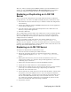
i.LON 100 Server LONWORKS +12V < 20mA Output Terminals
Connections
Screw Terminal Enclosure Marking +12V < 20mA
Connection
19 GND Ground
20 +12V < 20mA +12 Volt output.
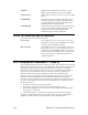
Applying Power to the i.LON 100 Internet Server
Once you have mounted the i.LON 100 Internet Server, connected all wiring, and
closed the enclosure, apply AC mains power to the unit. The LEDs on the i.LON
100 server will flash for several minutes as the unit boots. Once the unit is
powered and operational the green Power/Wink LED will stay solid ON.
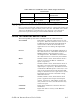
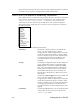
i.LON 100 Internet Server LEDs
The following LEDs provide status information for the i.LON 100 server.
Power/Wink This LED is on when the i.LON 100 server unit
has power. When the i.LON 100 server receives a
L
ONWORKS wink command, this light blinks on
and off 5 times. When the i.LON 100 server
applications are not running, this light blinks
rapidly.
Service Indicates the state of the LonTalk application in
the i.LON 100 server. This LED is normally off.
Blinking indicates the application is in the
unconfigured state. This LED is solid ON when
the i.LON 100 server is in Security Access Mode.
Meter 2 LEDs, labeled 1 and 2, which indicate when a
pulse is received on the Meter1 and Meter2
inputs, respectively.
Input 2 LEDs, labeled 1 and 2, which indicate when on
ON value is received on the Input1 and Input2
digital inputs, respectively. The LEDs are aware
of whether the Invert option is selected (i.e. if an
open circuit is interpreted as ON, then the light
will go on when the circuit is open and vice versa).
The digital input requires a minimum voltage
differential of 3.4V.
Output 2 LEDs, labeled 1 and 2, which indicate when
power is applied to the Output1 and Output2
outputs, respectively. The LED is on when the
relay contacts are closed, and off when the relay
contacts are open.
LAN Link Lights when an Ethernet connection has been
established.
LAN ACT Lights with there is activity on the Ethernet
connection.