i.LON™ 100 e2 Internet Server User’s Guide: Installing, Connecting, and Configuring the i.
Echelon, LON, LONWORKS, LonTalk, LonBuilder, LonManager, Neuron, 3120, 3150, LONMARK, NodeBuilder, and the Echelon logo are trademarks of Echelon Corporation registered in the United States and other countries. LonMaker, LNS, and i.LON are trademarks of Echelon Corporation.
Preface This document describes how to install and configure the i.LON 100 device in control and data networks. i.
Welcome This document describes how to install and configure the i.LON 100 device in control and data networks. Purpose The i.LON 100 User’s Guide: Installing, Connecting, and Configuring the i.LON 100 describes how to connect the i.LON 100 Internet Server hardware and configure it to communicate by TCP/IP, LONWORKS messaging, email, POP, and with Meter Bus devices. Related Documentation The i.LON 100 documentation is provided as online Adobe Acrobat PDF files and Windows Help files. The i.
• • • i.LON 100 Quick Start Guide — This document describes how to install the i.LON 100 Configuration Plug-in, how to connect the i.LON 100 hardware, and how to configure the i.LON 100’s IP information using the Web interface. i.LON 100 CD — This CD contains the installation software for the i.LON 100 Configuration Plug-in, as well as the installation software for LNS 3 Service Pack 7, Update 1, and LonMaker 3.1 Service Pack 2, Update 1. i.LON 100 License Agreement — The license agreement for the i.
• • • Applications Using the i.LON 100 Configuration Plug-in for more information. i.LON 100 Configuration Plug-in Support for custom type translator rules — Version 1.1 of the i.LON 100 Configuration Plug-in includes support for creating, modifying, and deleting rules used by the Type Translator functional block. See Chapter 7 in the i.LON 100 User’s Guide: Configuring the i.LON 100 Applications Using the i.LON 100 Configuration Plug-in for more information. i.
+12V < 20mA Output.....................................................................2-16 Applying Power to the i.LON 100 Internet Server................................2-17 i.LON 100 Internet Server LEDs.................................................................2-17 i.LON 100 Internet Server Buttons .............................................................2-18 FCC Compliance Statement – Class B ......................................................2-18 IC Compliance Statement – Class B.........
A The i.LON 100 Console Application A-1 The i.LON 100 Server’s Console Application .............................................. A-2 Console Command List......................................................................... A-2 Interrupting the Boot Process ............................................................... A-7 The Bootrom State ................................................................................ A-8 Updating the Bootrom ........................................................
1 Introduction This chapter provides an overview of the capabilities of the i.LON 100 server and the terminology used in this document. i.
Introduction The i.LON 100 Internet Server is a low-cost, high performance interface that connects LONWORKS based everyday devices to the Internet, a LAN, or a WAN. Appliances, meters, load controls, lights, security systems, pumps, valves – virtually any electrical device – can be connected through the i.LON 100 Internet Server to an IP network or the Internet. This allows a service center to configure, monitor, and control everyday devices from across the room, or across the globe. i.
• • • • • the i.LON 100 User’s Guide: Using the i.LON 100 Web Pages to Configure Applications and to Monitor and Control Data Points for more information. Pulse Metering – The i.LON 100 Internet Server contains 2 built-in pulse metering inputs. You can configure the i.LON 100 server to count pulses or to measure the pulse frequency. See the i.LON 100 User’s Guide: Configuring the i.LON 100 Applications Using the i.LON 100 Configuration Plug-in and the i.LON 100 User’s Guide: Using the i.
i.LON 100 server automatically have data points created for them (these are called local data points, or NVLs). When you add dynamic network variables to the i.LON 100 device, the i.LON 100 application automatically creates new local data points. The i.LON 100 server can also read and write the values of network variables on other LONWORKS devices in the network. In order to do this, you must create data points for these network variables (these are called external data points, or NVEs).
i.LON 100 RNI Limits The capabilities of the RNI on the i.LON-100 are in largely dependent on the software running on the host computer. When used as an LNS network interface, the i.LON-100 RNI has the following limits (see the Introduction to LonWorks document or the LonMaker User’s Guide for more information about these limits): • • • • • Up to 32768 address table entries. Up to 15 simultaneous transactions. Up to 1096 aliases. Up to 15 groups. Up to 4096 dynamic network variables. i.
2 Mounting, Cabling and Connections This chapter describes how to mount the i.LON 100 enclosure and how to attach power, data, a LONWORKS channel, an Ethernet network, and I/O to the i.LON 100 Internet Server. i.
Mounting the Enclosure ! Safety Warning The i.LON 100 Internet Server is intended to be mounted inside of a suitable, safety-agency approved enclosure that is mounted in a restricted access area. High-voltage wiring must be performed only by a qualified service person. The i.LON 100 Internet Server mounts to a 35mm x 7.5mm or 35mm x 15mm DIN rail located inside of a suitable, safety-agency approved enclosure, and mounted in a restricted access area.
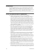
The following diagram shows the dimensions of the i.LON 100 server and the space required for the various connectors. All units are in millimeters: Wiring Connections The i.LON 100 Internet Server is provided with two rows of screw terminal wiring connections, an RJ45 data connection, an RJ11 telephone connection, and a DB-9 D-connector for connection to a configuration console.
LonTalk RS-485 Serial RS-232 Serial +12V <20 mA Digital Inputs RJ-45 10/ 100 Base T Ethernet Port Service Pin Reset Switch Mains (90-240 VAC, 50/60 Hz) Relay Outputs DB-9 Console Port RJ-11 Telephone Line Port Metering Inputs i.LON 100 Server Data, Console, and Telephone Connections The RJ-45 10/100 BaseT Ethernet Port The RJ-45 connector must be used with an RJ-45 male connector and a suitable Category 5 or Category 6 data cable connected to a 10BaseT or 100BaseT channel. The i.
i.LON 100 Server DB-9 Pin Assignment i.LON 100 DB-9 (DTE) Pin Description 1 NC (No connect) 2 RxD (Receive Data) 3 TxD (Transmit Data) 4 NC (No connect) 5 GND (Ground) 6 NC (No connect) 7 NC (No connect) 8 NC (No connect) 9 NC (No connect) DB-9 Shell Earth Ground The RJ-11 Telephone Line Port ! Safety Warning The i.LON 100 Internet Server telephone modem should be used only with telephone circuits equipped with proper lightning and transient protection circuitry.
• • • • • • High voltage mains power; Dry contact relay outputs; Pulse meter inputs; Digital inputs; LONWORKS network; +12V < 20mA Output; Each of these groups is described in detail below. RS-232/RS-485 Serial Ports The i.LON 100 includes one isolated RS-485 multi-drop bus port and one EIA-232 serial port. These ports can be used to connect the i.LON 100 to a GSM modem, to other computers, or to bus systems. To connect the i.
signals, it also supplies the M-Bus devices with power. (like the Echelon Link Power Transceivers). Depending on the number of M-Bus devices you are going to connect to the i.LON 100, different classes of level converters are available. There are converters that can drive only 3 M-Bus devices, and there are converters that can drive 20, 60, or even 250 devices. Examples and more information on these level converters can be found at: www.relay.de (Level Converter PW3, PW20, PW60) , www.stv-automation.
Safety Warning When connecting a unit, always connect earth ground first, then Neutral, then Line. This minimizes the risk of shock or damage should power inadvertently be present on Line. ! Safety Warning Fuse F350 in the i.LON 100 server uses a Wickmann rated 250 VAC, .5 A, SLO-BLO. ! Safety Warning The i.LON 100 server uses a Poly-carbonmonoflouride Lithium Coin battery. CAUTION: RISK OF EXPLOSION IF BATTERY IS REPLACED BY AN INCORRECT TYPE. DISPOSE OF UNUSED BATTERIES ACCORDING TO THE INSTRUCTIONS.
72104), for LONWORKS network signaling. The i.LON 100 server contains an auto-ranging, auto-setting mains power supply. It is not necessary to adjust any jumpers or other settings when connecting mains voltage. The high voltage connection is implemented on screw terminals 1 (earth ground), 3 (Neutral), and 4 (Line): screw terminal 2 (NC) is not used and should remain unconnected. A solid earth ground via terminal 1 connection is required for proper ESD and EMC performance of the i.LON 100 device.
! Safety and High Voltage Warning Ensure that the AC power mains are turned OFF before removing the cover, handling the mains wiring, or connecting any mains cabling to the i.LON 100 server device. DO NOT under any circumstances operate the i.LON 100 server device to mains voltages outside of the range 100/240VAC, -10% to +30%, 50/60Hz ±2.5Hz.
server, and may be triggered via the local software applications or based on the receipt of remote messages. The relay connections are implemented on screw terminals 5 through 8. The SPST relay contacts are not polarity sensitive and can be used to switch both AC and DC loads. The relays require a minimum load of 5V at 5mA in order to avoid low voltage contact pitting, and should therefore not be used to switch TTL level signals. i.LON 100 Server Relay Screw Terminals i.
Pulse Meter Inputs The i.LON 100 server is provided with two impulse meter inputs. These pulse meter inputs are in compliance with the DIN 43 864 impulse standard (open terminal voltage <12VDC, maximum current ≤27mA). The supervision of the inputs is under software control of the i.LON 100 server and its applications. The meter input connections are implemented on screw terminals 9 through 12. Meter 2 is connected to terminals 9-10 and Meter 1 is connected to 11-12.
i.LON 100 Server Pulse Meter Screw Terminals i.LON 100 Server Pulse Meter Connections Screw Terminal Enclosure Marking Pulse Meter Connection 9 Meter2- - signal from Meter 2 10 Meter 2+ + signal from Meter 2 11 Meter 1- - signal from Meter 1 12 Meter 1+ + signal from Meter 1 The pulse meter inputs can be connected to either a dry contact relay or to an active device output that generates pulses by closing the circuit between the two terminals.
Digital Inputs The i.LON 100 server has two optically isolated, polarity sensitive digital inputs that you can use for monitoring switches and sensors. The supervision of the inputs is under software control of the i.LON 100 server and its applications. The digital input connections are implemented on screw terminals 13 through 16. Input 2 is connected to terminals 13-14 and Input 1 is connected to 15-16.
LONWORKS Network The i.LON 100 server is provided with one of two types of LONWORKS channels: TP/FT-10 free topology twisted pair (Models 72101 and 72102) or PL-20 power mains (Models 72103 and 72104). The TP/FT-10 free topology twisted pair interface is polarity-insensitive and requires connecting the twisted pair to terminals 17 and 18. The PL-20 power mains interface is achieved via the 100-230VAC mains connection (see High Voltage Mains Power above). In some cases, on specially modified i.
i.LON 100 Server LONWORKS TP/FT-10 Free Topology Twisted Pair Terminals i.LON 100 Server LONWORKS TP/FT-10 Network Connections Screw Terminal Enclosure Marking LONWORKS Network Connection 17 LON B TP/FT-10 twisted pair 18 LON A / PLT Tap TP/FT-10 twisted pair +12V < 20mA Output The i.LON 100 server is provided with one +12V outlet that can provide up to 20mA. This +12VDC connection may be used by a set of dry contacts to power the optically isolated digital inputs.
i.LON 100 Server LONWORKS +12V < 20mA Output Terminals Connections Screw Terminal Enclosure Marking +12V < 20mA Connection 19 GND Ground 20 +12V < 20mA +12 Volt output. Applying Power to the i.LON 100 Internet Server Once you have mounted the i.LON 100 Internet Server, connected all wiring, and closed the enclosure, apply AC mains power to the unit. The LEDs on the i.LON 100 server will flash for several minutes as the unit boots.
LAN 100 Lights when the Ethernet connection is at 100 Mbps (power line models operate at 10 Mbps). LON Connect Lights when an xDriver session is open to an LNS Server. LON BIU/RX On the power line model, this is the band in use indicator; on the free topology model, this is the receive transmission indicator that lights when LONWORKS data is being received.
IC Compliance Statement – Class B This Class B digital apparatus meets the requirements of the Canadian Interference-Causing Equipment Regulations of ICES-003. VCCI Compliance Statement – Class B ITE This is a Class B product based on the standard of the Voluntary Control Council for Interference (VCCI) for information technology equipment. If this equipment is used near a radio or television receiver in a domestic environment, it may cause radio interference.
3 Installing the i.LON 100 Software, Hardware, and Firmware This chapter describes how to install the i.LON 100 Configuration Plug-in, how to connect the i.LON 100 hardware, and how to upgrade, back-up, and restore the i.LON 100 firmware. i.
Installing the i.LON 100 Software In order to access the i.LON 100 Web pages, you must have Internet Explorer 6 or later. To use the i.LON 100 Configuration Plug-in, you must install the i.LON 100 software. To install the i.LON 100 software, follow these steps: 1. Assure that you have LNS 3 SP 8 Update 1 (or later) and LonMaker 3.1 SP3 (or later). These patches are available on the i.LON 100 CD-ROM, in the following locations: LNS 3 SP8 D:\LNS SP8 xDriver\Lns3sp8_5a.
2. Assure that you have Internet Explorer 6, SP 1 (or later) installed on your computer. This is available on the i.LON 100 CD-ROM in the following location: D:\IE\ie6setup.exe 3. Once you have assured that the most recent LNS and LonMaker patches have been applied, open the root directory of the i.LON 100 CD and doubleclick Setup.exe. Follow the installation prompts to install the i.LON 100 software. Connecting and Configuring the i.LON 100 Internet Server To connect and configure your i.
This section describes the directory structure of the i.LON 100 firmware and how to backup, restore, replace, and upgrade the i.LON 100 firmware. The i.LON 100 Server’s Directory Structure The i.LON 100 server contains file system with a directory structure as described in this section. This directory structure is replicated on your computer in the LONWORKS\iLON100\Images\iLON100 1.10 directory. You can access the i.LON 100 server’s file system using an FTP client such as Internet Explorer.
ltConfig Contains LonTalk configuration data, including NVL driver bindings. Do not modify the files in this folder. Modules Contains module data. Do not modify the files in this folder. PulseBackup Contains backup data for the Pulse Counter functional block. Do not modify the files in this folder. Web Contains the data used to create the i.LON 100 Web pages. The file named “Index.htm” in this folder will be used as the default web page (“Index.html” will not work). See the i.
This way, when you back up the LonMaker database (see the LonMaker User’s Guide), you can set Backup All Files in Drawing Directory to backup the i.LON 100 configuration along with the rest of the LonMaker network. Restoring or Duplicating an i.LON 100 Server You can restore the configuration of an i.LON 100 device from an i.LON 100 backup directory. To restore an i.LON 100 backup directory, follow these steps: 1. Determine the location of the directory to which the i.LON 100 configuration was backed up.
10. Perform a replace operation. Using the LonMaker tool, right-click the i.LON 100 device shape and select Replace from the shortcut menu. 11. Follow the replace procedure as described in the LonMaker User’s Guide. Use the configuration property values from the old device. When prompted, press the service pin on the new i.LON 100 device. The new i.LON 100 device will now function exactly as the old one did. i.
4 Configuring the i.LON 100 This chapter describes how to configure the i.LON 100 using the i.LON 100 Web pages. For information on configuring the i.LON 100 applications using the Web pages, see the i.LON 100 User’s Guide: Using the i.LON 100 Web Pages to Configure Applications and to Monitor and Control Data Points. i.
Configuring the i.LON 100 Once you have connected your i.LON 100 as described in Chapter 3, configure it as described in the following steps: 1. Launch Internet Explorer 6 or later and point to http://192.168.1.222. The i.LON 100 Internet Server Welcome Web page appears. Click Login. 2. You will be prompted for a user name and password. By default, this is ilon/ilon. Once you supply this, the main menu Web page opens, as shown in the following figure: 3.
This Web page contains a list of all services configured on the LAN/WAN Web page (see Setting Up Connections, Servers, and Services Using the LAN/WAN Web Page). You can clear the associated checkbox to prevent verification of any item. To begin testing, click Start Tests. Any problems establishing communications with any of the servers will be reported. When initiating a remote test from this web page, the i.LON will be forced to dial out to each Dial-up connection that contains one or more services.
• • Hover your mouse cursor over Setup and select TCP/IP from the drop-down menu. This will open the LAN/WAN Web page with the LAN connection selected. See Configuring LAN Connection Properties, below, for more information on configuring the LAN connection. Hover your mouse cursor over Network and select LAN/WAN from the dropdown menu. This will open the LAN/WAN Web page with the top level of the tree (i.LON 100) selected.
• Applications and to Monitor and Control Data Points in for more information on web binding). Services – Each server can have one or more services that are available from the server. Each server can support one or more of the following services: • Email (SMTP) – This service is used to send email from the i.LON 100. See Configuring the Email (SMTP) Service, below, for more information. • WebBinder – This service is used to bind the i.LON 100 to another server.
connection, this property displays Not Connected. Host Name The TCP/IP host name of the i.LON 100 server. When the i.LON 100 server establishes a connection with an LNS Server it provides its fully qualified host/domain name so the LNS Server knows which LONWORKS database to open. By default, the i.LON 100 Internet Server’s host name is iLON100. The URL of the i.LON 100 server is Hostname.DNS Suffix (i.e. if Hostname is set to ilon100Alpha and Domain Suffix is set to ABCcorp.
2. Configure the following properties (all fields marked with an asterisk require a reboot before the new values take full effect): Automatically Obtain IP Address Set this option to have the i.LON 100 server obtain its IP address, subnet mask, and default gateway from the local network’s DHCP server.
local DHCP server. By default, this value is set to 192.168.1.222. Subnet Mask Subnet mask used by the i.LON 100 server if Manually Configure IP Settings is set. By default, this value is 255.255.255.0. Default Gateway Gateway used by the i.LON 100 server if Manually Configure IP Settings is set. By default, this value is 192.168.1.222. Default DNS Server/ Backup DNS Server The primary and secondary DNS servers used to resolve names (i.e. LNS Server name, DNS server name, hostname, etc.).
3. Configure the following properties: Connection Name Legal Characters: All ASCII characters except ‘&’, ‘<’, and ‘>’. Field Length: Up to 30 characters Enter a name for this dial-out profile, such as the name of the ISP. When Submit is clicked this name will appear in the tree on the left side of the LAN/WAN Web page. Phone Number Legal Characters: Digits and the hyphen character. Field Length: Up to 30 characters Enter the phone number to call for dial-out. By default, this field is blank.
Persistent GPRS If this option is selected, the GSM modem will request a network connection as soon as the i.LON boots, and keep the connection open as long as the service provider allows it. User Name Legal Characters: All ASCII characters except ‘&’, ‘<’, and ‘>’. Field Length: Up to 30 characters. Enter the user name to be used by the i.LON 100 server when connecting to an ISP. By default, this field is blank. Password/Reenter Password Legal Characters: All ASCII characters except ‘&’, ‘<’, and ‘>’.
2. Right-click the connection for which you want to create a server and select Add Server from the short-cut menu. The right-hand side of the LAN/WAN Web page will appear as shown in the following figure: 3. Set the IP Or Hostname for the server. This is the IP address or the hostname that will be used to contact the server. To access a server via hostname, DNS must be enabled on the i.LON 100 (see Configuring LAN Connection Properties, above). By default, this value will be 0.0.0.0. 4.
Configuring the Email (SMTP) Service If you select Email (SMTP) in step 3 of the Creating and Configuring Services procedure (above), you can send emails through the associated server (note that the server must be an SMTP email server). The right-hand side of the LAN/WAN web page will appear as shown in the following figure: This Web page contains the following options: Email Server Address The IP Address or hostname of the server to which this service applies.
Using the i.LON 100 Web Pages to Configure Applications and to Monitor and Control Data Points for more information). If you select WebBinder Destination in step 3 of the Creating and Configuring Services procedure (above), the associated server can be used as a WebBinder destination.
This Web page contains the following options: LNS Uplink Address The IP Address or hostname of the server to which this service applies. See Creating and Configuring Servers for more information. LNS Uplink Port The port used by the i.LON 100 to send LNS messages. By default, this value is 1628, but it may be changed to any valid port number. Contact your IS department to assure that your firewall is configured to allow you to access the LNS server on this port.
service created on the i.LON 100, this option will be enabled by default. If another time service is currently designated as the default, the designation will be removed from it when you click Submit. Click Submit to save the changes you have made to this Web page. Click Reset to leave all fields unchanged. Verifying i.LON 100 Connections The i.LON 100 Internet Server includes a Verify web page that is used to verify communications between the i.LON and LNS Servers, SMTP Servers, ISPs, other i.
from the i.LON 100, you must also create one or more dial-up connections, as described in Creating and Configuring a Dial-up Connection, earlier in this chapter. To support dial-in connections, you must set the Enable Dial-in option on the Security Web page (see Chapter 6). If your i.LON 100 Internet Server is equipped with a modem or attached to an external modem, configure it by hovering your mouse cursor over Setup and selecting Modem from the dropdown menu.
Password For Incoming Calls/Re-enter Password Field Length: Up to 30 characters. The password for incoming calls. This password must be provided by the caller when attempting to connect to the i.LON 100 server via modem. The password will appear as asterisks when entered. You must reenter the password to assure that you typed it correctly. By default, the password name is ilon.
Tone/Pulse This option only appears if you are using the internal analog modem. Set Tone or Pulse to determine whether the i.LON 100 internal modem will dial-out using touch-tone or pulse dialing. By default, this option is set to Tone. PIN Number This option only appears if you are using an external modem. Field Length: Up to 30 characters. Set the PIN Number that must be send to the external modem to send or receive calls.
The options on this page are divided into LonTalk Properties, NVE Driver Properties, LNS Uplink/Downlink Properties, and Initiate LNS Uplink Properties. These properties are discussed in the following sections: Configuring LonTalk Properties The following LonTalk properties are shown: Neuron ID Range The range of Neuron IDs used by the i.LON 100. This field is read-only. Channel Type The LonWorks Channel type supported by the i.LON 100. This is TP/FT-10 for FT model i.
as an RNI, reboot the i.LON 100, and re-establish an RNI connection. Configuring NVE Driver Properties The NVE driver properties determine how the i.LON 100 communicates with the network variables associated with NVE (external) data points (i.e. network variables on other devices that have i.LON 100 data points). See the i.LON 100 User’s Guide: Configuring the i.LON 100 Applications Using the i.LON 100 Configuration Plug-in for more information on creating and configuring NVE data points.
Delay Time Between Two Retries This option is not supported for LNS 3, Service Pack 8, Update 1, and earlier. This option is only available if Initiate LNS Uplink When IP Address Changes is checked. If the i.LON 100 attempts to inform the xDriver of an IP address change and is not successful, this is the amount of time before another attempt is made. Maximum Retry Time This option is not supported for LNS 3, Service Pack 8, Update 1, and earlier.
This Web page contains the following options: Default/Backup Time Server These read-only fields display the IP address/hostname and port of the default and backup SNTP time servers. Click Configure to open a popup window that allows you to create a new time server (see Creating and Configuring Servers for more information about servers) Time of Last SNTP Sync This read only field shows when the i.LON 100 last synchronized its clock with the Default Time Server. How often the i.
Driver from the drop-down menu. The M-Bus Driver Web page opens, as shown in the following figure: 3. Click the Add button. A new M-Bus device is added to the page, as shown in the following figure: 4. Enter the following information: Name The name of the data point to be associated with the M-Bus device. Once a name has been assigned (i.e. the Submit button has been clicked), it cannot be changed. This name can be up to 30 characters long and must begin with “MBS_”.
Bus device will update the data point on the i.LON 100 at the specified interval. M-Bus devices cannot send event-driven updates, so they must be polled. This value can be set from 0.0 to 6553.4 seconds, with a resolution of .1 seconds. Setting this value to 0.0 will turn off polling. By default, this value is 30 seconds. Click Help for more information on using this web page. See Chapter 7 of the i.LON 100 User’s Guide: Configuring the i.LON 100 Applications Using the i.
5 Managing the i.LON 100 This chapter describes how to reboot the i.LON 100, how to clean the i.LON 100 (i.e. restore manufacturer settings), and how to view i.LON 100 system information. i.
Rebooting the i.LON 100 Server You can reboot the i.LON 100 server using the Reboot Web page. Click the Reboot button to begin the reboot. A Web page will be displayed telling you that the i.LON 100 server is rebooting. A reboot takes approximately 2 minutes. While the reboot is happening, the LEDs on the i.LON 100 server will flash; once the reboot is complete, the green Power/Wink LED will stay on solidly. Once the reboot is completed, the Welcome Web page will open.
SNTP servers: 0.0.0.0 Time zone: (GMT-08:00) Pacific Time (US & Canada); Tijuana LNS Servers: 0.0.0.0:1628 Incoming RNI port: 1628 LonTalk address: unconfigured Email server: 0.0.0.0 Source email address: [blank] CENELEC enabled: false (Power line model only) All XML configuration files, as well as the contents of the /root/PulseBackup (pulse count data), /root/AlarmLog (alarm log data), and /root/data (data log data) directories will be backed up to a /root/config/software.bak.
i.LON 100 Model Information This section of the System Info Web page displays i.LON 100 model information. This information may be requested by Echelon support when diagnosing a problem with the i.LON 100. This part of the web page shows the following information: Model Number The model number of the i.LON 100. Channel Type The channel type of the i.LON 100. Either TP/FT10 or PL-22. Modem Installed Indicates whether the i.LON 100 has an internal modem. CPU Speed The CPU speed of the i.LON 100, in MHz.
It should be noted that the block erase limit specified by the flash manufacturers is very conservative. Empirical testing of at least some flash parts indicates that a typical limit under normal conditions may be at least 10 times longer, which translates to a much longer life for the i.LON 100 flash disk, and/or erase rates much greater than 39 erases per minute. Informally, flash manufacturers will confirm these findings, but they cannot be guaranteed.
number of available spare blocks on your i.LON 100 may vary. This does not adversely affect the normal operation of the flash disk, as long as some spares are available. When the number of spare flash blocks falls below the recommended limit of eight blocks, this value will be shown in red and a warning message will be displayed at the top of the web page. If a flash block on the i.LON 100 fails and there are no spare blocks remaining, the flash disk may become unreliable. The i.
6 i.LON 100 Security This chapter explains how to configure i.LON 100 security and describes how to perform a security access reset. i.
i.LON 100 Server Security The i.LON 100 Internet Server institutes a number of security measures: • • • MD5 Authentication. When functioning as an RNI, the i.LON 100 Internet Server uses MD5 authentication with all communications between it and the LNS Server, requiring a 16-byte authentication key. Security Web Page. The i.LON 100 Security Web page allows you to password protect or disable entirely FTP, Web server, dial-in, and RNI access to the i.LON 100 server. Security Access Reset.
place it on the 192.168.1.* subnet or enter the following command in the Windows Command Prompt window: route add 192.168.1.0 mask 255.255.255.0 %COMPUTERNAME% This command allows your computer to communicate with the i.LON 100 server even when they are not on the same subnet. This command does not persist through computer reboots, but you can add it to the startup script for your computer. When in security access mode you can access the Security and Restore Factory Defaults Web pages. The i.
Enable FTP Set this option to allow FTP access to the i.LON 100 server. Set the port the i.LON 100 will use for FTP communication in the Port column. By default, this option is enabled and the port is set to 21. Enable Web Server Set this option to allow HTTP access to the i.LON 100 server. Set the port the i.LON 100 will use for FTP communication in the Port column. Note: If you disable this option, you will not be able to access the i.LON 100 Web pages after a reset.
7 Configuring the i.LON 100 Internet Server as an RNI This chapter describes how to use the i.LON 100 server as a remote network interface (RNI) and how to configure the xDriver settings. For more information on the xDriver, see the LNS Programmer’s Guide – xDriver Extension. i.
Using the i.LON 100 Server as a Remote Network Interface The i.LON 100 server can be used as a remote network interface (RNI). This allows the i.LON 100 server to take the place of a standard LONWORKS interface (i.e. PCLTA-20, PCC-10, etc.). The LNS Server sends LONWORKS messages over IP to the i.LON 100 server, which is connected to the rest of the LONWORKS network (either TP/FT-10 or PL-20 power line). This function can be performed simultaneously with the application and Web server abilities of the i.
To use the LONWORKS Interfaces Control Panel applet, follow these steps: 1. Open the Windows Control Panel and double-click the LONWORKS Interfaces icon ( ). This opens the LONWORKS Interfaces Control Panel applet. NOTE: This is not the same as the LONWORKS/IP Channels Control Panel applet used with the i.LON 1000 Internet Server. 2. The applet lists the LNS network interface names of all the network interfaces that have been added to the Windows registry below the Default item.
NOTE: You must be logged in as a user with administrative rights to create a registry entry for an i.LON 100 server if you are using the Windows 2000 or Windows XP platforms. 3. Enter the name for the new RNI. This will be used as a lookup key to access the proper registry entry each time xDriver initiates a connection to this RNI. Each RNI must have a unique name. 4. Click OK. This opens the tab shown in the following figure: 5. Configure the fields on the General tab.
Description Comments: Optional field. Generally used to describe the site. 6. When you have configured the fields on the General tab, click the Address/Port tab. This opens the tab shown in the following figure: 7. Configure the fields on the Address/Port tab. The following table describes these fields. Field i.Lon is listening on port: Description Default Value: 1628 Range: 1-65,535 Comments: Enter the TCP port number the i.LON 100 server is using to listen for incoming connections from the LNS Server.
When you have configured the fields on the Address/Port tab, click the Authentication tab. This opens the tab shown in the following figure: 8. You can choose to authenticate connections to this i.LON 100 using a specified MD5 authentication key or an MD5 authentication key that is derived from a specified text secret phrase using an algorithm configured into the i.LON 100. Using an MD5 authentication key or text secret phrase prevents the LNS Server and the i.
You can modify an i.LON 100 server’s settings later by selecting it from the list of network interfaces, and clicking the Network Interface Properties button. You can remove an i.LON 100 server from the Windows registry by selecting it from the list, and clicking the Network Interface Remove button. Switching Between i.LON 100 RNI and a Standard LONWORKS Network Interface If you are using the i.LON 100 server as an RNI and wish to switch to a different LONWORKS network interface (e.g.
• i.LON 100 Server Security in Chapter 6 for more information about the Security Web page and security access reset. Enter the following command using the console application: deactivate 4 4 is the index of the RNI application. Confirm that you want to disable the RNI application. Disabling the RNI application may cause the i.LON 100 server to reboot. See Appendix A for more information about the console application. If you want to use the RNI capability of the i.
Appendix A The i.LON 100 Console Application This appendix describes how to use the i.LON 100 Server’s console application through the serial port. i.
The i.LON 100 Server’s Console Application You can use the i.LON 100 server’s console application to configure and troubleshoot the i.LON 100. To access the console application, you must connect a female-to-female DB-9 null modem crossover cable from the Console hardware output to a COM port on your computer; then use a terminal emulator, such as Windows HyperTerminal, to communicate on the specified serial port.
demo A|B Reserved for future use. dhcp on|off Turns DHCP on and off. If DHCP is on, the i.LON 100 DHCP client gets its IP address, gateway, subnet mask, primary DNS server (if used), and DNS domain from a DHCP server. diag Module subcommand [params] Performs diagnostic commands on the i.LON 100 server. You may be asked to perform these commands by Echelon support personnel to assist them in diagnosing problems with your i.LON 100 server. The module argument must be set to ConMan (connection manager).
dialuptrace [level] Sets the dialup trace level. This command is a simpler version of the diag ConMan trace command described above. You may be asked to perform a dialup trace by Echelon support personnel to assist them in diagnosing problems with your i.LON 100 server. The higher the trace level, the more information will be displayed by the console application. Available dialup trace levels are: 0 or OFF – Turns off dialup tracing.
DnsServerViaDhcp – Obtaining DNS Server from DHCP. DnsDomainViaDhcp – Obtaining DNS suffix via DHCP. eventlog on|off Turns the console event log on and off. The event log is kept in eventlog.txt in the root directory of the i.LON 100 server. factorydefault Resets the i.LON 100 server to its factory defaults. Files added by the user outside of the /root/software directory (i.e. Web pages) are not affected. Echelon highly recommends that user run this command from the i.LON 100 bootrom console.
[dmn]sn nd the application specified by idx. Caution! This command is provided for backward compatibility to add an i.LON 100 server to a pre-installed network. Echelon does not recommend or support using this command. The i.LON 100 server should be installed using a standard network installation tool such as the LonMaker tool. ipaddress address Modifies the IP address. For example, ipaddress 101.253.100. This command is valid only when DHCP is turned off.
modules. sntpaddress address Modifies the address of the SNTP server. If you have a backup SNTP server, you can enter sntpaddress address1 address2. sntplog on|off Enables or disables SNTP logging. The SNTP log file is named sntp.log and is located in the root directory of the i.LON 100 server. The time logged in the SNTP log file is in universal coordinated time (UTC). The maximum size of the SNTP log file is 50 Kbytes. When the file exceeds 50 Kbytes, logging is automatically disabled.
(Additional information about the corrections is written to the event log file.) The boot process then loads the i.LON 100 server’s system image. Successful completion is indicated when the i.LON 100 server displays its normal commandline prompt. If the i.LON 100 server repeatedly fails to boot up, you are unable to FTP files to it, or you suspect the image is corrupted, you may interrupt the boot process to troubleshoot the i.LON 100 server.
Appendix B Troubleshooting i.LON 100 Configuration This appendix can be used to diagnose common problems that occur during i.LON 100 configuration. i.
Anytime I reboot or power down and up when using RNI loose connection in LonMaker and have to un-attach and reattach. • This is a known bug that will be addressed in a future release. The current work around is to close and then re-open the system. I can access my i.LON 100 Web pages but some content seems to be missing. • The i.LON 100 has been designed to work with Microsoft Internet Explorer 6.0 or later. Some pages will not display correctly on other browsers or prior versions of IE.
The i.LON 100 gets a duplicate IP address assigned from a DHCP server, and either boots using its default IP address (i.e. 192.168.1.222), or boots using the duplicate IP address. • • If the i.LON 100 device boots using its default IP address when it has obtained an address via DHCP, it is probably because the DHCP server assigned an address already in use by another machine on the network.