i.LON™ 100 e2 Internet Server Programmer’s Reference Version 1.
Echelon, LON, LONWORKS, NodeBuilder, LonTalk, Neuron, LONMARK, LNS, LonBuilder, LonUsers, BeAtHome, LonManager, 3120, 3150, LonPoint, Digital Home, LONWORLD, ShortStack, i.LON, the Echelon logo, and the LONMARK logo are registered trademarks of Echelon Corporation. LNS Powered by Echelon, LonMaker, LonLink, LonResponse, OpenLDV, LONews, Open Systems Alliance, Panoramix, Panoramix Powered by Echelon, LONMARK Powered by Echelon, Powered by Echelon, and LonSupport are trademarks of Echelon Corporation.
Table Of Contents 1 Introduction to the i.LON 100 SOAP/XML Interface.............................................. 1-1 1.1 About This Document .................................................................................................... 1-1 1.2 Programming Samples .................................................................................................. 1-2 1.3 Getting Started ..............................................................................................................
.8 5 Getting Started ............................................................................................................ 4-14 Data Server....................................................................................................................... 5-1 5.1 Data Server XML Files .................................................................................................. 5-4 5.1.1 DP_NVL.XML .............................................................................................
9.2.1.4 10 AnalogFBDelete .............................................................................................. 9-15 Event Scheduler ............................................................................................................ 10-1 10.1 EventScheduler.XML................................................................................................... 10-2 10.2 Creating and Modifying the EventScheduler.XML File............................................ 10-4 10.2.
1 Introduction to the i.LON 100 SOAP/XML Interface The i.LON 100 contains a powerful microprocessor with a real-time, multi-tasking operating system that manages its various applications. These applications include alarming, scheduling, data logging and network variable type translation. Generally, you will configure these applications using the i.LON 100 Configuration Software, as described in the i.LON 100 Internet ServerUser’s Guide. The i.
You can create or modify the files using any XML editor or ASCII text editor. This document provides examples you can use when creating the XML configuration files for your i.LON 100, and instructions to follow when downloading these files to the i.LON 100. The XML files used by the i.LON 100 applications conform to the XML 1.0 Technical Recommendation: http://www.w3.org/TR/2000/REC-xml-20001006 Echelon strongly recommends that you use the SOAP interface to configure the applications of your i.LON 100.
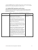
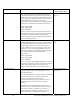
1.0 of the SOAP/XML interface. An i.LON 100 using version 1.1 software will accept and respond to SOAP messages sent by applications written with version 1.0 of the SOAP/XML interface just as an i.LON 100 using version 1.0 software would. 1.4.1 Modified SOAP Applications and Functions Table 1 lists the functions and properties that have been modified for version 1.1 of the SOAP/XML interface. Each function includes a brief explanation of how the function or property was modified for version 1.1.
Function AlarmGeneratorGet Description of Change For More Information, See… The i.LON 100 has been modified to handle the properties defining the hysteresis levels and offset limits used by each Alarm Generator differently for certain data types. This only applies if you use the AlarmGeneratorGet function to return the configuration of an Alarm Generator with input data points that use the following format descriptions: AlarmGeneratorGet on page 7-5.
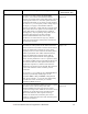
Function Description of Change For More Information, See… DataServerRead In version 1.0 of the i.LON 100 SOAP/XML interface, you could use the DataServerRead function to read the value of any data point, or group of data points. However, each data point had to be specified individually, by its name or index number. In version 1.1, you can specify a time stamp range in the input you supply to the DataServerRead function so that the i i.
1.4.2 Changes to SOAP Message Formats The SOAP body that must be included in every message sent to the i.LON 100, and in every output message returned by the i.LON 100, has been updated in version 1.1. The namespace URI has been modified to reflect the new version number of the i.LON 100. In addition, the SOAP header attached to response messages sent by the i.LON 100 will include the time the message was sent, the IP address of the i.
2 SOAP Messages and the i.LON 100 WSDL File This chapter contains general information about the SOAP/XML interface you will need to know before using the SOAP functions described in this manual. It includes the following major topics: • i.LON 100 WSDL File. An overview of the i.LON 100 WSDL file, which defines the SOAP/XML interface. When writing applications to use the SOAP interface, some tools can import this file and automatically build a class structure for sending and receiving each message.
authenticate access to Web pages that send or receive multiple SOAP messages. If a SOAP message is sent to the i.LON 100 that does not contain the correct user name and password, it will be ignored. For instructions on using the i.LON Web Server Security and Parameters utility, see Chapter 13 of the i.LON 100 Internet Server User‘s Guide. To protect FTP access to the XML configuration files, the i.LON 100 requires a user name and password for every FTP session.
http://www.w3.org/TR/2000/NOTE-SOAP-20000508/ The SOAP envelope portion of the sample input message shown above includes the following: ... You will notice that the fourth line of this example includes the symbol “...” This is where the portion of the message known as the SOAP body would be.
document includes a sample XML string you could supply as the parameter, and a description of how to build the XML string. However, there are a few exceptions to this rule. The DataPointRead, DataPointWrite, and DataPointResetPriority functions do not include a parameter as part of their input messgaes. They take a series of input parameters, each of which contains a single value, as input.
standards mentioned in the previous section. Every element in a SOAP Header, and all immediate child elements must be namespace qualified. Therefore, each user defined element contains a namespace prefix and a path to the unique Echelon Namespace. The SOAP Header consists of a complex type with four fields describing different properties of the message: • This field contains a time stamp indicating when the message was sent. • This field contains the Neuron ID of the i.
Error Code Error Message 0 No Error 1 Unknown function call. 2 Parameter error. For example, the input you supplied to the function does not contain valid data, or no data was supplied to the function. 3 XML/Parser Error. 4 Tag missing. 5 Index missing 6 Index not found 7 Index invalid The index number you supplied to the function is greater than the maximum or less than the minimum allowed by the application. The allowable range of index numbers in the i.LON 100 is –32,768-32,767.
3 Monitoring and Controlling Data Points with the SOAP/XML Interface Any i.LON 100 user can make use of the SOAP/XML interface, even those who do not plan on using it to configure the applications of their i.LON 100. The SOAP interface includes functions that read and write the values of the data points defined on the i.LON 100. These functions do not affect the configuration of the i.LON 100 applications.
point. This property is updated by the Data Server in real time, and can be read or written to with the functions described in this chapter. 3.2 About This Chapter This chapter describes the syntax of each of the functions you can use to read and write to the values of the data points in your network. It also includes code samples written in Microsoft Visual Basic .NET that may be useful when designing applications that use these functions.
3.3 DataPointWrite You can use the DataPointWrite function to write to the value of any data point in your network. You must reference the data point to be modified by the name (UCPTpointName) assigned to it in i.LON 100 Data Server in the input you supply to the function, as in the example below. The of a data point is defined when it is created and added to the i.LON 100 Data Server. You can create data points with the i.LON 100 Configuration Software or with the DataServerSet function.
Property Description Enter the of the data point to be written to. The name must begin with the following prefixes: • NVL_ for an NVL data point • NVC_ for an NVC data point Note: The names assigned to NVL data points follow the naming convention NVL_[NAME], where [NAME] represents that progammatic name assigned to the NV when it was created with LONMAKER.
Property Description 0 or 1. If you assign the default value 1 to the property, the change you make to the data point value will be propagated over the network. If you assign value 0 to this property, the change will be made in the i.LON 100 Data Server, but not over the network.
Event Custom Application Invokes DataPointResetPriority Priority Level Assigned 255 Result of Operation The custom application invokes the DataPointResetPriority function to reset the priority level assigned to the data point. This does not result in a change in the data point’s value, but the priority level assigned to the data point is reset to 255, the lowest priority. At this point, all applications will be able to write to the data point.
3.4 DataPointRead You can use the DataPointRead function to retrieve the current value assigned to a data point, as well as the values of several properties associated with the data point. You can use this function with any data point in your network. You must reference the data point whose you value you want to read by its name (UCPTpointName) in the input you supply to the function, as in the example below.
Property Description Enter the of the data point to be written to. The name must begin with the following prefixes: • NVL_ for an NVL data point • NVC_ for an NVC data point Note: The names assigned to NVL data points follow the naming convention NVL_[NAME], where [NAME] represents that progammatic name assigned to the NV when it was created with LONMAKER.
Property Description The value definition being used by the data point. If the data point is not using a value definition, or if you defined the property in the input you supplied to the function, this field will appear blank. Value definitions are user-defined strings that represent preset values the data point can be updated to. For example, the value assigned to a value definition called ON for a SNVT_switch data point might be “100.0 1.
3.5 DataPointResetPriority You can use the DataPointResetPriority function to reset the priority level of a data point to 255, the lowest priority level. This would allow any application to write to the value of the data point. You must reference the data point to be affected by its in the input you supply to the function, as in the example below.
3.6 Using the DataPoint Functions With Visual Basic .NET You can call the DataPoint functions from development environments such as Microsoft Visual Basic .NET by referencing the i.LON 100 WSDL file. Chapter 14, Using the SOAP Interface as a Web Service, describes how to reference the i.LON 100 WSDL file in Microsoft Visual Basic .NET. This chapter describes the syntax you will use when you call each of these functions, and provides a code sample written in Visual Basic .NET that invokes each of them. 3.6.
Input Parameters For descriptions of the input parameters that you must supply to the function, see DataPointResetPriority on page 3-10. Returns: The function returns a string containing the name of the data point reset by the function. 3.6.4 Programming Samples The following programming sample, written in Microsoft Visual Basic .NET, invokes all three of the DataPoint functions. It uses the DataPointWrite function to write to the value of a data point called NVL_nvo01Switch.
'Call DataPointWrite, and then call DataPointResetPriority. Note 'that the priority 'level used in the call to 'DataPointResetPriority is less than that used in the call to 'DataPointWrite. This resets the priority assigned to 'NVL_nvo01Switch to 255, and allows all other applications to write 'to the data point. The propagate value used is in each call is 1, 'so that the change is updated over the network. retWrite = ilon.
4 i.LON 100 Applications and the SOAP/XML Interface This chapter provides an overview of the applications supported by the i.LON 100, and of how you can use the SOAP/XML interface to configure these applications and use the data they generate. This chapter includes the following major sections: • Overview of i.LON 100 Applications. This section provides a description of each of the applications that the i.LON 100 supports. • i.LON 100 XML Configuration Files. The configuration of each i.
triggered them. Alarms can be configured to shut off automatically when certain conditions are met, or they can be configured to require manual clearance. You will create Alarm Generators and Alarm Notifiers to manage these alarming tasks. Table 6 provides a brief description of the functions you can use to do so. These functions are described in detail in Chapters 7 and 8 of this document.
As an alternative to using SOAP, you can modify the files manually using an ASCII-text or XML editor, and then download them to the i.LON 100 via FTP. Echelon does not recommend this, as you will need to reboot the i.LON 100 for it to read the downloaded files, and the i.LON 100 will not perform error-checking on the downloaded XML files. Chapters 5-13 of this document describe the content of each of the i.
Function Names DataloggerList DataloggerGet DataloggerSet DataLoggerRead DataLoggerClear DataloggerDelete Description Use the DataLoggerList function to return the index number, last update time, description, and functional block name of each Data Logger that you have added to the i.LON 100. You can use the DataLoggerGet function to return the configuration of any of these Data Loggers. Use the DataLoggerSet function to add new Data Loggers to the i.
Function Names EventSchedulerList EventSchedulerGet EventSchedulerSet EventSchedulerDelete Description Use the EventSchedulerList function to return the index number, last update time, description, and functional block name of each Event Scheduler that you have added to the i.LON 100. You can use the EventSchedulerGet function to return the configuration of any of these Event Schedulers. Use the EventSchedulerSet function to add new Event Schedulers to the i.
This input is a string of encoded XML containing a list of objects, or the desired settings of any number of the configuration properties associated with the i.LON 100. The contents of the string vary by function. The string of encoded XML contained within the parameter is the single parameter you will supply as input when calling the SOAP functions described in Chapters 5-13 of this document.
• & character is replaced by & For both the and parameters (see next section), the SOAP application will handle the value as a string. This string can be directly decoded and manipulated by an XML parsing engine. All input strings passed over the network in the parameter must be valid, encoded XML, and all strings returned by the i.LON 100 within the parameter will be passed over the network as valid, encoded XML.
4.4 i.LON 100 Resource Files There are many configuration properties you can configure using the SOAP functions described in this document. This document provides a general description of each property, and other information you will need when configuring each one, such as minimum and maximum values for scalar properties, and maximum string lengths for string properties. This information is also contained in the i.LON 100 resource files. In order to successfully send a SOAP message to the i.
directory /root/lonworks/types, and are named STANDARD.ENU, STANDARD.TYP, STANDARD.FMT and STANDARD.FPT. Many configuration properties that are used by the i.LON 100 applications are based on the SCPTs defined in these files. The information provided in this document, and in the SCPT resource files, will help you determine what values to assign to the SCPTs referenced by the i.LON 100. You can browse the entire SCPT device resource files online at http://types.lonmark.org. 4.4.
4.5 Data Formatting In order to keep the i.LON SOAP/XML interface neutral across regions, most of the rules for formatting data, which would normally be changeable in LNS, are not changeable on the i.LON 100. The one exception is the support of measurement system locale which is new in version 1.1. The following list describes the various regional settings used by the i.LON 100 SOAP / XML interface: Decimal Symbol – Always period ".
4.6 List, Get, Set and Delete Functions The SOAP interface for each i.LON 100 application contains a List function, a Get function, a Set function, and a Delete function. Together, these functions make up a symmetric interface. You can use the response from the List command as the input to the Get command. You can use the response from the Get command as the input to the Set command.
After its initial invocation, you can use the AlarmGeneratorSet function to overwrite the values of the global properties defined for the Alarm Generator application. You can also use it to add new Alarm Generators to the XML file, or to overwrite the configuration of exisiting Alarm Generators. Each time you create an Alarm Generator (or any item or instance of an i.LON 100 application) using the Set method, the item will be assigned an index number.
4.7 Performance Issues The i.LON 100 contains 32 MB of RAM, which allows for complicated application configurations and extensive network use. However, even with this amount of memory, it is still possible for very high levels of network traffic to the i.LON 100, especially using the SOAP interface, to eventually exhaust its memory. This could result in delays in network access of the i.LON 100, performance problems for the i.LON 100 applications, or in the worst case even a reboot of the i.LON 100.
4.8 Getting Started Chapters 5-13 of this document provide more detailed information on the various applications of the i.LON 100, and describe the SOAP functions you can use to configure them. You should review Chapter 5 before attempting to program any of the i.LON 100 applications. This chapter introduces and describes the i.LON 100 Data Server, which manages the data points you will use to control your network.
5 Data Server The i.LON 100 uses the concept of a data point to map logical names to i.LON 100 system variables, network variables defined on the i.LON 100 LonTalk interface, and explicitly addressed network variables. This paradigm can be extended to handle data from other types of control networks as drivers for these buses become available. Data points provide the i.
i.LON 100 Applications: Alarm Notifier Alarm Generator Data Logger Analog Function Block Event Scheduler Event Calendar Type Translator Web Binder The various applications of the i.LON 100 can be configured using the i.LON 100 configuration software and LONMAKER, as well as the SOAP/XML interface: Custom Applications Using the i.LON 100 SOAP/XML Interface i.LON 100 Configuration Software The i.LON 100 applications poll the Data Server for NVE and MBus data point values and information. i.LON 100 i.
notified each time the data point is updated. In this fashion, each application has current access to all the network information pertaining to the data points it is using. This chapter describes how to create data points and add them to the Data Server. NOTE: Echelon recommends that you restrict all networks to a maximum of 800 data points. i.
5.1 Data Server XML Files The /root/config/software/dataserver directory of your i.LON 100 contains several XML files that will store the configuration of the data points in your Data Server. Table 7 describes these XML files. Table 7 Data Server XML Files File Name Description DP_NVL.XML When a local NV for the i.LON 100 is created using LONMAKER, a corresponding NVL data point is automatically added to the Data Server. Its configuration can then be modified using the SOAP interface or the i.
5.1.1 DP_NVL.XML The DP_NVL.XML file is created automatically the first time the i.LON 100 boots. It will contain an element for each static NV on the device. The properties contained within these elements define the configuration of an NVL data point, and are described later in this chapter. Each time you use LONMAKER to create a dynamic network variable for the i.LON 100, an element for the associated data point will be added to this file.
2 NVL_nvoDlClear iLON SNVT_switch 2 BT_STRUCT % of full level state code 0.0 0.0 0.0 0.
5.1.2 DP_NVC.XML The DP_NVC.XML file contains a list of elements, one for each NVC data point that you have added to the Data Server. An NVC data point represents an i.LON 100 system variable that maintains a constant value. Each element defines the configuration of an associated NVC data point. The properties that must be defined within each element define the configuration of an NVC data point, and are described later in this chapter. The following represents a sample DP_NVC.XML file for an i.
5.2 Creating and Modifying the Data Server XML Files The i.LON 100 generates all of the Data Server configuration files the first time it boots. The DP_NVL.XML file will contain an element for each static NV on the device that has been created with LONMAKER. New NVL data points will be added to the DP_NVL.XML file automatically when more local NVs are created in LONMAKER. The DP_NVC.XML file will not contain any data point entries the first time the i.LON 100 boots.
Function Description DataServerResetPriority Use this function to reset the priority level assigned to a data point. For more information, see DataServerResetPriority on page 5-25. DataServerDelete Use this function to remove a data point from the Data Server. For more information, see DataServerDelete on page 5-28. i.
5.2.1.1 DataServerList Use the DataServerList function to retrieve a list of data points that you have added to the i.LON 100 Data Server. The Data Server List function accepts an empty string as the contents of its parameter. If you supply an empty string as the parameter, the list returned by the function will contain an entry for every data point in the Data Server.
The interval resets each time the value of a data point is retrieved. By default this value is 0 for NVL data points, and 0 NVC data points. You can change this value by manually modifying it in the DP_NVL.XML or DP_NVC.XML configuration files. Note that you can also temporarily override this value each time you call the DataServerRead function. See the DataServerRead function later in this chapter for more information.
5.2.1.2 DataServerGet You can use the DataServerGet function to retrieve the configuration of any data point that you have added to the i.LON 100 Data Server. Each NVL data point to be returned must be identified by an element within the parameter, and each NVC data point must be identified by an element. You must reference the specific data point to be returned by its index number (UCPTindex) or its name (UCPTpointName) within each of these elements, as shown below.
DIR_OUT 100.0 1 0.0 0 The DataServerGet function returns an element for each data point referenced in the parameter you supplied to the function. The properties included within each element are initially defined when the data point is added to the DataServer. You can write to them with the DataServerSet function. Table 10 describes these properties.
Property Description The format description of the data point. This determines many factors about the data point, including the type of values it takes, and its base type. This could be any standard (SNVT) format type included in the i.LON 100 resource files, or any user-defined (UNVT) format type included in resource files uploaded to the i.LON 100. For more information on the i.LON 100 resource files, see i.LON 100 Resource Files on page 4-8.
Property Description This property applies to output data points, and defines the minimum amount of time that may elapse between data point updates if it set to a non-zero value. For example, if a SNVT_temp value data point is changing by one degree every half second and this value is set to two seconds, the data point will only be updated every two seconds with the latest value, even though the value changes more frequently than that.
Property Description Optional. This value is initially taken from the i.LON 100 resource files, if it exists for the data point type selected. This value represents the maximum value the data point can be updated to. NOTE: You can use DataServerSet to change this limit in the Data Server. However, you must program your application to enforce the new limit, as the i.LON 100 will continue to enforce the limit taken from the resource files. Optional.
5.2.1.3 DataServerSet Use the DataServerSet function to overwrite the configuration of an NVL or NVC data point, or to create an NVC data point and add it to the Data Server. Each NVL data point to be written to must be identified by an element within the parameter, and each NVC data point must be identified by an element. You must reference the specific data point to be written by its index number (UCPTindex) or its name (UCPTpointName) within each of these elements, as shown below.
Parameter 200 NVL_nvo01Switch Light Kitchen Lamp Kitchen 230V; 100W SNVT_switch BT_STRUCT State, % 60 10 100.0 1 0.
5.2.1.4 DataServerRead You can use the DataServerRead function to read the value and status of any data point that you have added to the Data Server. There are two ways to reference the data points whose values and statuses are to be returned: • You can reference each data point to be read by its index number or name in the parameter you supply to the function. If the specified input data point is a structure, you can specify the field whose value is to be returned below.
0 NVL_nvo03Switch 9 state Parameter 5-20 i.
5.2.1.4.2 Requesting Data Points by Type and Last Update Time You can also reference the data points to be returned by their data point type, and time of last update. This may be useful if you want to see which data points were updated during a certain time period, or if you want to read the values of all data points of a certain type. Table 11 DataServerRead Input Properties Property Description Enter the type of data point you want to see information for.
NVL 2001-07-01T00:00:01.000+00:00 2001-07-31T23:59:59.999+00:00 20 Parameter 5.2.1.4.3 DataServerRead Output Properties The function returns an element for each data point referenced in the parameter you supplied to the function.
Property Description If the value of a field was requested in the parameter, this property contains the name of the field. A timestamp indicating the last time the value of the data point was updated. This timestamp is expressed in local time, with an appended time zone indicator that indicates the difference between local time and Coordinated Universal Time (UTC). UTC is the current term for what was commonly referred to as Greenwich Meridian Time (GMT).
5.2.1.5 DataServerWrite A data point's value and priority level are initially set when the data point is added to the Data Server. The value is set to the value established for the property for the data point, and the priority defaults to the lowest priority level (255). You can use the DataServerWrite function to update the value and priority of one or more data points at a time.
Parameter 8 10 state 5.2.1.5.1 DataServerWrite Fault Responses As of version 1.1, the i.LON 100 will return a detailed fault response message if it fails to update the value of any of the data points specified in the parameter.
of Fault Response Message 421 NVL NVL_myNetworkVar_1 11 Value cannot be formatted 422 NVL NVL_myNetworkVar_2 11 Value cannot be formatted
5.2.1.6 DataServerResetPriority You can use the DataServerResetPriority function to reset the priority of a data point to 255, the lowest priority. Each NVL data point to be reset must be identified by an element within the parameter, and each NVC data point must be identified by an element. You must reference the specific data point to be reset by its index number (UCPTindex) or its name (UCPTpointName) in each of these elements, as shown below.
5.2.1.7 DataServerDelete You can use the DataServerDelete function to remove a data point from the Data Server. Each NVL data point to be deleted must be identified by an element within the parameter, and each NVC data point must be identified by an element. You must reference the specific data point to be deleted by its index number (UCPTindex) or its name (UCPTname) in each of these elements, as shown below. The deletion of NVL data points requires two steps.
6 Data Loggers You can use Data Loggers to monitor activity on your network. Each Data Logger will record updates to a group of user-specified data points into a log file. The information recorded for each update includes the value and status that the data point was updated to. Each i.LON 100 supports up to ten Data Loggers. The log files for each Data Logger are stored in the /root/Data directory of the i.LON 100 with the file name logX, where X represents the index number assigned to the Data Logger.
1 1 0 2002-02-12T14:36:51Z Data Logger 0 LT_CIRCULAR 100 LF_BINARY 0.0 0 NVL_nviWHTot1 0.
1 NVL_nviWeekend 10.0 0 10 2 NVL_nvoWeekday 10.0 0 10 i.
6.2 Creating and Modifying the DataLogger.XML File You can create and modify the DataLogger.XML file with the DataLoggerSet SOAP function. The following section, DataLogger SOAP Interface, describes how to use DataLoggerSet and the other SOAP functions provided for the Data Logger application. Alternatively, you can create and modify the DataLogger.XML file manually and download it to the i.LON 100 via FTP. Echelon does not recommend this, as the i.
6.2.1.1 DataLoggerList Use the DataLoggerList function to retrieve a list of the Data Loggers that you have added to the i.LON 100. The DataLoggerList function takes an empty string as its parameter, as in the example below. The function returns the major and minor version numbers of the firmware implementation that the Data Logger application is using in the parameter. The parameter also includes a element for each Data Logger that you have added to the i.LON 100.
6.2.1.2 DataLoggerGet You can use the DataLoggerGet function to retrieve the configuration of any Data Logger that you have added to the i.LON 100. You must reference the Data Logger whose configuration is to be returned by its index number in the parameter you supply to the function, as in the example below.
Property Description The index number assigned to the Data Logger must be in the range of 0-32,767. As mentioned earlier, you can use the DataLoggerSet function to create a new Data Logger, or to modify an existing Data Logger. If you do not specify an index number in the parameter you supply to DataLoggerSet, the function will create a new Data Logger using the first available index number.
Property Description Enter a value between 0.0 and 100.0. The default value is 0.0. This value represents a percentage. When the volume of the Data Logger reaches this percentage, the status of the output data point for the Data Logger will be updated to the condition AL_ALM_CONDITION. The output data point for each Data Logger is called NVL_nvoDlLevAlarm[X], where X represents the index number assigned to the Data Logger. For example, if you enter 30.
Property Description This property applies to scalar data points only. Specify the change in value required for an entry to the log to be made. For example, if this property is set to 30.0, the value of the data point being monitored must change by at least 30.0 during an update for the change to be recorded by the Data Logger. All updates are logged if this value is 0.0, or not defined. This property has minimum and maximum floating point values of +/-3.402823466e+038.
6.2.1.3 DataLoggerSet Use the DataLoggerSet function to create new Data Loggers, or to overwrite the configuration of existing Data Loggers. The Data Loggers to be created or written to are signified by a list of elements in the parameter. The properties you must define within each element are the same, whether you are creating a new Data Logger or modifying an existing Data Logger. The previous section, DataLoggerGet, describes these properties.
6.2.1.4 DataLoggerRead Use the DataLoggerRead function to retrieve the entries in the log files generated by your Data Loggers. You can specify which log entries the function will return by filling the properties described in Table 16 into the parameter you supply to the function. Table 16 Property DataLoggerRead Input Properties Description The index number of the Data Logger to return log entries for.
6.2.1.4.1 Local Times and Coordinated Universal Time The timestamps for the and properties conform to the ISO 8601 standard. They are expressed in local time, with appended time zone indicators that show the relationship to the Coordinated Universal Time (UTC ). UTC is an international time standard and is the current term for what was commonly referred to as Greenwich Meridian Time (GMT).
Parameter 2 /root/data/log2.dat 2002-08-29T10:30:11.000-07:00 2002-08-29T14:34:20.000-07:00 2003-08-29T14:34:20.000-07:00 8.5 57 NVL_nviDlCount2 iLON100 0.
Property Description This property contains a timestamp indicating the last time an entry in the log file was deleted with the DataLoggerClear function, or the last time an entry in the log was modified with the DataLoggerWrite function. The timestamp is displayed in local time, with an appended time zone indicator that indicates the difference between local time and UTC. For more information on this, see Local Times and Coordinated Universal Time on page 612.
6.2.1.5 DataLoggerClear You can use the DataLoggerClear function to remove log entries from a Data Logger’s log file. You can specify which Data Logger is to be affected, and which log entries will be removed, by configuring the properties described in Table 19 into the parameter you supply to the function. NOTE: This function only deletes the log entries. You can delete the Data Logger itself with the DataLoggerDelete function.
Parameter 2 NVL_nviDlCount2 2002-01-27T00:00:00.000+01:00 2002-11-28T00:00:00.000+01:00 3 Parameter 2 /root/data/log2.dat 2002-08-29T10:32:00.000-07:00 2002-08-29T14:34:20.
6.2.1.6 DataLoggerDelete You can use the DataLoggerDelete function to delete a Data Logger. You must reference the Data Logger to be deleted by its index number in the parameter you supply to the function, as in the example below. Parameter 0 Parameter 0 i.
7 Alarm Generator Use the Alarm Generator application to generate alarms based on the values of the data points in your network. Each time you create an Alarm Generator, you will select an input data point and a compare data point. The Alarm Generator will compare the values of these data points each time either one is updated. You will select the function the Alarm Generator will use to make the comparison.
7.1 AlarmGenerator.XML The AlarmGenerator.XML file stores the configuration of the Alarm Generators that you have added to the i.LON 100. Each Alarm Generator is signified by an element in the XML file. You can create new Alarm Generators using the AlarmGeneratorSet SOAP function, or by manually editing the AlarmGenerator.XML file, and rebooting the i.LON 100. The sections following this example provide instructions and guidelines to follow when doing so.
7.2 Creating and Modifying the AlarmGenerator.XML File You can create and modify the AlarmGenerator.XML file with the AlarmGeneratorSet SOAP function. The following section, Alarm Generator SOAP Interface, describes how to use AlarmGeneratorSet, and the other SOAP functions provided for the Alarm Generator application. Alternatively, you can create and modify the AlarmGenerator.XML file manually using an XML editor, and download the file to the i.LON 100 via FTP. Echelon does not recommend this, as the i.
7.2.1.1 AlarmGeneratorList Use the AlarmGeneratorList function to retrieve a list of the Alarm Generators that you have added to the i.LON 100. The AlarmGeneratorList function takes an empty string as its parameter, as in the example below. The function returns the major and minor version numbers of the firmware implementation that the Alarm Generator application is using in the parameter.
7.2.1.2 AlarmGeneratorGet You can use the AlarmGeneratorGet function to retrieve the configuration of any Alarm Generator that you have added to the i.LON 100. You must reference the Alarm Generator whose configuration is to be retrieved by its index number in the parameter you supply to the function, as in the example below.
element are initially defined when you create the Alarm Generator. You can write to them with the AlarmGeneratorSet function. Table 22 describes these properties. When creating or writing to an Alarm Generator with the AlarmGeneratorSet function, all properties are mandatory unless otherwise noted. For more information on the AlarmGeneratorSet function, see AlarmGeneratorSet on page 7-16.
Property Description Specifies the alarm priority that will be reported in the priority_level field of the alarm data points for the Alarm Generator. The alarm priority is independent of the alarm type. For a list of valid alarm priorities, see Alarm Priority Levels on page 7-11. The time period to wait after enabling or starting the application before polling the value of the input data point. This field has a range of 0.06553.0 seconds.
Property Description The input data point for this Alarm Generator. The data point must be referenced by its . Each time this data point is updated, its value will be compared to the value of the compare data point using the comparison function defined by the property. If the result of the comparison is True, an alarm will be generated.
Property Description Optional. These properties define the Alarm Generator’s alarm data points. Each data point must be referenced by the assigned to it in the Data Server. The data point chosen for the must use the format type SNVT_alarm. The data point chosen for the must use the format type UNVT_alarm2. Use a SNVT_alarm data point if your system can handle this LonMark standard type for alarming.
Property Description Specifies the time period to wait after the condition that caused an alarm has returned to normal status before the alarm will be cleared. You must use the following format for this property: DAYS HOURS:MINUTES:SECONDS.MILLISECONDS For example, 0 6:22:12.333 indicates a time period of 6 hours, 22 minutes and 12.333 seconds. The maximum value you can enter is: 0 1:59:59.999 The default value is: 0 00:00:00.
Property Description When an alarm occurs based on one of the offest limits described above, the value of the input data point must reach the hysteresis value for that limit before the alarm can be cleared, and another alarm can be generated based on that offset limit.
Identifier Notes PR_10 HVAC Critical Equipment RTN, Fire RTN (Display) PR_16 HVAC RTN (lowest priority) PR_NUL Value not available 7.2.1.2.2 Comparison Functions Table 24 describes the comparison functions an Alarm Generator can use when comparing the values of the input and compare data points. You can select a comparison function for the Alarm Generator by filling in the property.
You can make inequality comparisons between SNVT_switch (BT_STRUCT) data points, or between SNVT_lev_disc (BT_ENUM) data points. Table 26 lists the identifiers you could use for these special comparisons. A description of how these comparisons are made follows Table 26.
Table 28 Alarm Generator Hysteresis Levels Offset Limit Causing Alarm Alarm Cleared When...
The following diagram depicts the four different alarm conditions, as well as the corresponding hysteresis levels that must be reached to clear the alarms generated for each condition, in a line chart. Please note that the diagram uses enumerations to label the hysteresis levels the input value must reach for each alarm status to be cleared. For example, AL_HIGH_LMT_CLR_2 represents the value necessary to clear the AL_HIGH_LMT_ALM_2 alarm status.
7.2.1.3 AlarmGeneratorSet You can use the AlarmGeneratorSet function to create a new Alarm Generator, or to overwrite the configuration of an existing Alarm Generator. You can create up to 40 Alarm Generators per i.LON 100. The Alarm Generators to be created or written to by the function are signified by a list of elements in the parameter.
50.00 75.00 50.00 75.00 Parameter 2 7.2.1.4 AlarmGeneratorDelete You can use the AlarmGeneratorDelete function to delete an Alarm Generator.
8 Alarm Notifier Use the Alarm Notifier application to log user-defined alarm conditons, and to generate email messages and data point updates each time an alarm condition occurs. This section provides an overview of how Alarm Notifiers work, including how you can define alarm conditions and program your Alarm Notifiers to respond to them. User-Defined Alarm Conditions When you create an Alarm Notifier, you will specify a group of input data points.
Auto-Generated Log Files Each Alarm Notifier will generate its own log file. It will add an entry to this log file each time it generates an alarm notification. You can find these log files in the /root/AlarmLog directory of the i.LON 100. These files are named histlogX, where X represents the index number assigned to the Alarm Notifier when it was created. An Alarm Notifier will not generate a log file until it has generated an alarm notification.
0 NVL_nvoLevelAlarm 0 1 0 0 0 0 0 1 7 log level of data logger 1 0 Joerg js@nova occured %dy/%dm/%dd Nofifier1: %ad
8.2 Creating and Modifying the AlarmNotifier.XML File You can create and manage the AlarmNotifier.XML file with the AlarmNotifierSet SOAP function. The following section, Alarm Notifier SOAP Interface, describes how to use AlarmNotifierSet and the other SOAP functions provided for the Alarm Notifier application. Alternatively, you can create and manage the AlarmNotifier.XML file manually with an XML editor and download it to the i.LON 100 via FTP. Echelon does not recommend this, as the i.
8.2.1.1 AlarmNotifierList Use the AlarmNotifierList function to retrieve a list of the Alarm Notifiers that you have added to the i.LON 100. The AlarmNotifierList function takes an empty string as its parameter, as in the example below. The function returns the major and minor version numbers of the firmware implementation the Alarm Notifier application is using in the parameter. The parameter also includes an element for each Alarm Notifier that you have added to the i.
8.2.1.2 AlarmNotifierGet You can use the AlarmNotifierGet function to return the configuration of any Alarm Notifier that you have added to the i.LON 100. You must reference the Alarm Notifier whose configuration is to be returned by its index number in the parameter you supply to the function, as in the example below.
AL_NO_CONDITION AL_NUL 0 NVL_nviWeekday 0 NVL_nvoAlarmFlag1 77.
Property Description The index number assigned to the Alarm Notifier must be in the range 032,767. As mentioned earlier, you can use the AlarmNotifierSet function to create a new Alarm Notifier, or to modify an existing Alarm Notifier. If you do not specify an index number in the parameter you supply to AlarmNotifierSet, the function will create a new Alarm Notifier using the first available index number.
Property Description The size of the historical alarm log file, in kilobytes. The historical alarm log contains a record for any acknowledged alarm. Each record includes the description, acknowledgment time and comment entered for the alarm. Please note that the total size of the log files for all Alarm Notifiers (and Data Loggers) on the i.LON 100 can not exceed the size of the flash memory stored in the i.LON 100. The i.
Property Description If the input data point is updated and matches the conditions defined by any of the active alarm condition sets, it is considered an active alarm. In this case, the Alarm Notifier will use its active destinations. You can create as many active alarm condition sets as you want per Alarm Notifier. The active alarm condition sets for an Alarm Notifier are signified by a list of elements.
Table 32 Property Input Data Point Properties Description The index number to be used within the Alarm Generator application for this data point. This does not have to match the index number assigned to the data point in the i.LON 100 Data Server. The name of the data point, as defined in the i.LON 100 Data Server. i.
Property Description This field is a series of seven Boolean values (0,1) separated by spaces that determine what information will be stored in the Alarm History and Alarm Summary Logs for this data point. The meanings of each byte in the string are described below: Byte 1 (log_enable): When this byte is set to 0, each new alarm will be recorded in the Alarm History Log when it initially occurs. No further entries will be recorded into the log for the alarm.
Property Description The group number for alarm notifications caused by this data point. You can use group numbers to categorize alarms. Alarm groups can be numbered from 1 to 127. The priority level to be assigned to the data point when it reaches an alarm condition. This must be an integer between 0 (high priority) and 255 (low priority). You can use priority levels to sort the alarms with the summary log view, or with the i.LON 100 Web pages. The default value is 0.
Property Description The path can be a maximum of 1024 characters long. Table 34 lists the macro arguments you can use to fill in the property within each mail element. Table 34 Macro Arguments Macro Argument Description %al Alarm type. This is the current status (UCPTpointStatus) of the data point that caused the alarm. %at Alarm type number. This is the integer value that maps to the point status (UCPTpointStatus) that defines the alarm type.
Macro Argument Description %tm The minute that the alarm occurred. %ts The second that the alarm occurred. %th The millisecond that the alarm occurred. %ti The time that the alarm occurred, expressed in the following format: HH:MM:SS For example, 08:12:22 indicates an alarm time of 8 AM, 12 minutes and 22 seconds. %va The current value of the data point that caused the alarm. %ad The alarm description.
Property Description Enter an alarm level for the condition set, in the range 0-255. The level assigned to a condition set will determine which alarm destinations will be used when an alarm occurs that is based on that condition set. For each alarm destination you create, you will specify a range of levels. For example, you could set up one destination set for the alarm conditions using levels 0-125, and another for the alarm conditions using levels 126-255.
Every should contain one or more and elements. Table 36 describes the properties you must define for each and element. Each element defines an active destination set for the Alarm Notifier. Each element defines a passive destination set for the alarm notifier.
Property Description The delay, in minutes, to wait for an alarm to be acknowledged before sending an e-mail to the e-mail profile for the destination. If the alarm is not acknowledged before this time expires, the e-mail profile will be used. The default value used if this property is not set is 0. In this case, the e-mail profile will be used as soon as the alarm occurs. The maximum is 65,535. 8-18 i.
8.2.1.3 AlarmNotifierSet Use the AlarmNotifierSet function to create new Alarm Notifiers, or to overwrite the configuration of exisiting Alarm Notifiers. The Alarm Notifiers to be created or written to are signified by a list of elements in the parameter. The properties that you must define within each element are the same, whether you are creating a new Alarm Notifier or modifying an existing Alarm Notifier. The previous section, AlarmNotifierGet, describes these properties.
1 Log 30 percent full AL_ALM_CONDITION 0 255 Normal Condition AL_NUL 0 NVL_nviWeekday 0 Headquarters NV
Table 37 Parameter AlarmNotifierRead Input Properties Description Enter the name of the data point you want to see log entries for. Leave this property blank to see log entries for all data points the Alarm Notifier is monitoring. Enter HISTORICAL to return the contents of the Alarm History Log, which contains a log entry for every alarm notification made by the Alarm Notifier.
Parameter Description Use these fields to specify a range for the log time of the entries that will be returned by the function. You can specify a start and stop time, or just a stop time. When reading the Alarm History Log, these fields indicate a range for the log time of the entries in the log, which is stored for each entry in the property.
Parameter 1 NVL_AlarmGenIn1 HISTORICAL 2002-01-01T00:00:00.000+01:00 2002-09-04T23:59:59.
Properties Description The name of the log file the Alarm Notifier is using. When reading the Alarm History Log, these properties contain timestamps indicating the log time of the first and last entries in the log file. When reading the Alarm Summary Log, these properties contain timestamps indicating the alarm time of the first and last entries in the log file.
Property Description The network address of the device the data point is local to. This is displayed using the following format: [Subnet.Node] The location of the data point. The alarm text for the alarm. This text can be specified for an Alarm Notifier using the AlarmNotifierSet function. The priority level assigned to the data point that caused the alarm.
Property Description The status of the alarm. This can be AUTO_ACK or MANUAL_ACK for an acknowlegded alarm that has not been removed from the active alarms list, AUTO_CLEAR or MANUAL_CLEAR for an alarm that has been acknowledged but not removed from the active alarm list, and NACK for an alarm that has not yet been acknowledged. You can clear or acknowledge alarms manually with the AlarmNotifierWrite function. For more information, see AlarmNotifierWrite on page 8-26.
Property Description You can select one of four parameters to change the alarm status entered in the log: • MANUAL_CLEAR : Alarm will be acknowledged and removed from the active list. • MANUAL_ACK: Alarm will be acknowledged, but not removed from the active list. • NACK: Alarm will not be acknowledged or removed from the active list. However, the comment entered for the property will be entered into the log.
Table 41 Property AlarmNotifierWrite Output Properties Description The index number of the Alarm Notifier affected by the function. The type of log file affected by the function: SUMMARY or HISTORICAL. The name and path of the log file affected by the function. The and properties indicate the time the alarm time of the first and last entries in the log file.
8.2.1.6 AlarmNotifierClear Use the AlarmNotifierClear function to clear a group of log entries from an Alarm Notifier log file. This function only deletes the log entries. You can delete the Alarm Notifier itself with the AlarmNotifierDelete function. You can specify which alarm entries are to be cleared out by filling the properties described in Table 42 into the parameter you supply to the function. If you do not fill in these properties, the entire alarm log will be cleared.
Parameter 0 NVL_nviBgtVa 2001-01-31T14:30:00.000+03:00 2001-02-28T14:30:00.000+03:00 200 Parameter 0 SUMMARY /root/AlarmLog/sumlog0.dat 2001-01-31T14:30:00.
8.2.1.7 AlarmNotifierDelete You can use the AlarmNotifierDelete function to delete an Alarm Notifier. You must reference the Alarm Notifier to be deleted by its index number in the parameter you supply to the function, as in the example below. Parameter 9 Parameter 9 i.
9 Analog Function Block You can use Analog Function Blocks to perform a variety of statistical operations on the values of the data points in your network, and store the result of each operation in an output data point. You can perform these operations on as many input data points as you like per Analog Function Block.
1 0 2002-06-02T09:16:36Z Bielefeld Analog Fn Block- 0 FN_GT 100 FN_MAX 10.0 80.0 0.
9.2 Creating and Modifying the AnalogFB.XML File You can create and modify the AnalogFB.XML configuration file with the AnalogFBSet SOAP function. The following section, Analog Function Block SOAP Interface, describes how to use the AnalogFBSet function and the other SOAP functions provided for the Analog Function Block application. Alternatively, you can create and modify the AnalogFB.XML file manually with an XML editor and download it to the i.LON 100 via FTP. Echelon does not recommend this, as the i.
9.2.1.1 AnalogFBList Use the AnalogFBList function to retrieve a list of the Analog Function Blocks that you have added to the i.LON 100. The AnalogFBList function takes an empty string as its parameter, as in the example below. The function returns the major and minor version numbers of the firmware implementation the Analog Function Block application is using in the parameter.
9.2.1.2 AnalogFBGet You can use the AnalogFBGet function to retrieve the configuration of any Analog Function Block that you have added to the i.LON 100. You must reference the Analog Function Block whose configuration is to be displayed by its index number in the parameter you supply to the function, as in the example below.
The function returns an element for each Analog Function Block referenced in the parameter you supplied to the function. The properties included in each element are initially defined when the Analog Function Block is created. You can write to them with the AnalogFBSet function. Table 45 describes these properties. For more information on the AnalogFBSet function, see AnalogFBSet on page 9-14.
Property Description This property defines the comparison function the Analog Function Block will use to compare the values of the compare data point and the input data points. This function will only be used if the selected is FN_COMPARE, FN_OR or FN_AND, and if the property is not defined. These properties are described later in the table.
Property Description The delay, in seconds (0.0 to 6553.0), that must elapse between updates to the Analog Function Block’s output data point. This may be useful if you have multiple input data points, as setting a long interval here could cause the Analog Function Block to only update the output data point when all inputs have been received. If you use the default value of 0.
Property Description You can specify as many input data points as you want per Analog Function Block. The input data points for an Analog Function Block are defined by a list of elements in the parameter supplied to the function. For each element, you must specify an index number to be used within the Analog Function Block (UCPTindex), the name of the data point (UCPTpointName), and the interval to use when polling the data point’s value (UCPTpollRate).
Property Description This element defines the output data point for this function block. You must specify the assigned to the output data point within this element. The value of this data point will be updated with the result of each comparison or statistical operation that the Analog Function Block performs. 9.2.1.2.1 Output Functions Table 46 lists and describes the output functions you can use to fill in the property.
Identifier FN_NUL Value Assigned To The Output Data Point Value not available. 9.2.1.2.2 Comparison Functions Table 47 lists and describes the comparison functions you can use to fill in the property. You must reference each function by the identifier listed in the table. Table 47 Comparison Function Identifiers Identifier Description FN_GT Greater than.
Table 48 Input 1 Input 2 Input 3 Input 4 9 11 12 13 20 30 40 50 20 70 30 80 40 40 50 50 FN_AND Examples Value of Compare Data Point Does not matter since is defined. Does not matter since is defined. UCPTtrueThreshold 35 35 Output 10 0.0 0 10 100.0 1 EMPTY EMPTY 0.0 0 100.0 1 9.2.1.2.
property if it is defined, for this to happen. If the is defined then the value of the compare data point is not used in the comparison. Table 50 lists several case scenarios that show when these two functions might evaluate to True. Table 50 Input 1 50 Input 2 30 Input 3 50 Input 4 50 40 40 40 40 50 50 50 50 50 50 50 49 FN_COMPARE Examples Value of Compare Data Point Does not matter since is defined. Does not matter since is defined.
9.2.1.3 AnalogFBSet Use the AnalogFBSet function to create new Analog Function Blocks, or to overwrite the configuration of existing Analog Function Blocks. The Analog Function Blocks to be created or written to are signified by a list of elements in the parameter. The properties that you must define within each element are the same, whether you are creating a new Analog Function Block or modifying an existing Analog Function Block.
value 0 NVL_nvoClsValue_1 value Parameter 1 9.2.1.4 AnalogFBDelete You can use the AnalogFBDelete function to delete an Analog Function Block.
10 Event Scheduler You can use the Event Scheduler application to schedule periodic updates to the data points in your network. You will select a data point, or group of data points, for each Event Scheduler you create. These data points will be updated to specific values on the dates and times that the Event Scheduler is effective. The dates and times that the Event Scheduler is active, as well as the values the Event Scheduler will update the data points to, are completely user-defined.
After a restart, the Event Scheduler recalculates the last Event Scheduler operation. It also sets the data point NVL_nvoDateResync to “100.0 1”, and then to “0.0 0”, which updates the i.LON 100 exception list. You can set the value of NVL_nvoDateResync to “100.0 1” with the DataPointWrite or DataServerWrite function at any time to refresh the exception list manually. The data point NVL_nviEcResync of the Event Calendar will be internally bound to NVL_nvoDateResync if no external binding is created.
1,0,0,0,0,0,1 0 100.0 1 12:30 1 0.
10.2 Creating and Modifying the EventScheduler.XML File You can create and modify the EventScheduler.XML file with the EventSchedulerSet SOAP function. The following section, Event Scheduler SOAP Interface, describes how to use EventSchedulerSet and the other Event Scheduler SOAP functions. Alternatively, you can create and modify the EventScheduler.XML file manually with an XML editor, and download it to the i.LON 100 via FTP. Echelon does not recommend this, as the i.
10.2.1.1 EventSchedulerList Use the EventSchedulerList function to retrieve a list of the Event Schedulers that you have added to the i.LON 100. The EventSchedulerList function takes an empty string as its parameter, as in the example below. The function returns the major and minor version numbers of the firmware implementation that the Event Scheduler application is using in the parameter.
10.2.1.2 EventSchedulerGet You can use the EventSchedulerGet function to return the configuration of any Event Scheduler that you have added to the i.LON 100. You must reference the Event Scheduler whose configuration is to be returned by its index number in the parameter you supply to the function, as in the example below.
0 Datumbasierend 25 0 OnValue 14:0 1 OffValue 15:30 0 Holiday
Property Description A timestamp indicating the last time the configuration of the Event Scheduler was written to. This timestamp uses the following format: YYYY-MM-DDTHH:MM:SSZ The first segment of the time stamp (YYYY-MM-DD) represents the date the configuration of the Event Scheduler was last updated. The second segment (THH:MM:SS) represents the time of day the configuration of the Event Scheduler was last updated, in UTC (Coordinated Universal Time).
Property Description The data points that will be updated by the Event Scheduler are defined by a list of elements in the parameter. For each element, you must enter the name (UCPTpointName) of the data point to be updated. In addition, you should fill in the delay time (SCPTdelayTime) property for each data point. This integer value represents the period of time, in seconds, that must elapse before this data point is updated based on a DayBased or DateBased schedule point.
Property Description The priority assigned to the schedule, from 0 (highest priority) to 255 (lowest priority). The priority chosen here must be greater than or equal to the current priority level assigned to a data point when the Event Scheduler attempts to update that data point. If it is not, the data point will not be updated successfully. For a more detailed description of data point priority levels, see Data Point Values and Priority Levels on page 3-5.
ON 03:40 OFF 18:40 10.2.1.2.2 Creating a Date-Based Schedule Table 54 lists and describes the properties that should be defined within each element.
Property Description The update events for each date-based schedule are signified by a list of elements. Each update event will be used on the days that this date-based schedule is active. For each element, you must enter a value, or select a value definition defined for the data points the Event Scheduler is updating, as the property. You can define value definitions for each data point with the DataServerSet function.
10.2.1.3 EventSchedulerSet You can use the EventSchedulerSet function to create new Event Schedulers, or to overwrite the configuration of existing Event Schedulers. The Event Schedulers to be created or written to are signified by a list of elements in the parameter. The properties you must define within each element are the same, whether you are creating a new Event Scheduler or modifying an existing Event Scheduler.
240 1,0,0,0,0,0,1 0 100.0 1 12:30 1 0.
10.2.1.4 EventSchedulerDelete You can use the EventSchedulerDelete function to delete an Event Scheduler. You must reference the Event Scheduler to be deleted by its index number in the parameter you supply to the function, as in the example below. You can delete more than one Event Scheduler with a single call to EventSchedulerDelete, if desired. The following example deletes two Event Schedulers, one using index value 0 and one using index value 1.
11 Event Calendar Use the Event Calendar application to define the exception points that you will reference when creating the date-based schedules for your Event Schedulers. Each exception point you create represents a date, or a group of dates. When you reference an exception in an Event Scheduler, you will be able to assign the dates for that exception a unique schedule.
0 2002-06-26T10:44:27Z Floor Calendar 1 0000-00-00,0000-00-00 0 Holiday 0 0000-04-07,0000-06-07,MN_NUL,DY_NUL 0
11.2 Creating and Modifying the EventCalendar.XML File You can create and modify the EventCalendar.XML file with the EventCalendarSet SOAP function. The following section, Event Calendar SOAP Interface, describes how to use the EventCalendarSet function and the other SOAP functions provided for the Event Calendar application. Alternatively, you can create and modify the EventCalendar.XML file manually with an XML editor, and download it to the i.LON 100 via FTP. Echelon does not recommend this, as the i.
11.2.1.1 EventCalendarList Use the EventCalendarList function to retrieve a list of the Event Calendars that you have added to the i.LON 100. The EventCalendarList function takes an empty string as its parameter, as in the example below. The function returns the major and minor version numbers of the firmware implementation that the Event Calendar application is using in the parameter.
11.2.1.2 EventCalendarGet You can use the EventCalendarGet function to return the configuration of any Event Calendar that you have added to the i.LON 100. You must reference the Event Calendar whose configuration is to be returned by its index number in the parameter you supply to this function, as in the example below.
Property Description A timestamp indicating the last time the configuration of the Event Calendar was updated. This timestamp uses the following format: YYYY-MM-DDTHH:MM:SSZ The first segment of the time stamp (YYYY-MM-DD) represents the date the configuration of the Event Calendar was last updated. The second segment (THH:MM:SS) represents the time of day the configuration of the Event Calendar was last updated, in UTC (Coordinated Universal Time).
11.2.1.2.1 Creating an Exception Point The exception points for an Event Calendar are defined by a series of element. Table 57 describes the properties that must be defined within each element. Table 57 Exception Point Properties Property Description The name of the exception point. This can be a maximum of 27 characters long. You will use this to reference the exception point from the Event Scheduler application. Either 0 or 1.
Table 58 DAY_T Identifiers Identifier Description DY_LAST_DAY_OF_MONTH Last day of month DY_LAST_SECOND_DAY Second-to-last day of the month. DY_LAST_THIRD_DAY Third-to-last day of the month NOTE: There are many other identifiers that use the DY_LAST_XXX_DAY format described by the last three identifiers. XXX represents an integer specifying the exact day to use, in the range of 4-30.
Identifier Description DY_FOURTH_FRI Fourth Friday of each month DY_FOURTH_SAT Fourth Saturday of each month DY _FIFTH_SUN Fifth Sunday of each month DY_FIFTH_MON Fifth Monday of each month DY_FIFTH_TUES Fifth Tuesday of each month DY_FIFTH_WED Fifth Wednesday of each month DY_FIFTH_THURS Fifth Thursday of each month DY_FIFTH_FRI Fifth Friday of each month DY_FIFTH_SAT Fifth Saturday of each month DY_LAST_SUN Last Sunday of each month DY_LAST_MON Last Monday of each month DY_LAST_TUE
Table 59 MONTH_T Identifiers Identifier Description MN_JAN January MN_FEB February MN_MAR March MN_APR April MN_MAY May MN_JUN June MN_JUL July MN_AUG August MN_SEP September MN_OCT October MN_NOV November MN_DEC December MN_EVERY_MONTH Every month during the interval the Event Calendar is active. MN_EVERY_2_MONTHS Every other month during the interval the Event Calendar is active. MN_QUARTERLY Every third month during the interval the Event Calendar is active.
The following string would set up an exception that occurs every day from 2000/2/28 until 2000/3/5: 2000-02-28,2000-03-05,DY_NUL,MN_NUL The following string would set up an exception that occurs every second day from 2000/2/28 until 2000/3/5: 2000-02-28,2000-03-05,DY_EVERY_SECOND,MN_NUL The following string would set up an exception that occurs on the last Saturday of each month between 2000/2/26 and 2002/4/29: 2000-02-26,2002-04-29,DY_LAST_SAT,MN_NUL The following string would set up an exception that is v
11.2.1.3 EventCalendarSet You can use the EventCalendarSet function to create new Event Calendars, or to overwrite the configuration of existing Event Calendars. The Event Calendars to be created or written to are signified by a list of elements in the parameter. The properties you must define within each element are the same, whether you are creating a new Event Calendar or modifying an existing Event Calendar.
11.2.1.4 EventCalendarDelete You can use the EventCalendarDelete function to delete an Event Calendar. You must reference the Event Calendar to be deleted by its index number in the parameter you supply to the function, as in the example below. Parameter 0 Parameter 0 i.
12 Type Translator You can use Type Translators to convert data points from one network variable type to another. This may be useful when comparing data points from different vendors that use different types, and are not compatible with each other. When creating a Type Translator, you will choose a Type Translator Rule. The Type Translator Rule defines the network variable type of the data points the Type Translator will take as input, and the network variable type it will convert these data points to.
1 1 1 2002-05-14T12:42:54Z Translator For SNVT_Lev_Disc Type Translator- 1 SNVT_lev_disc_TO_SNVT_switch 0.
12.2 Creating and Modifying the TypeTranslator.XML File You can create and modify the TypeTranslator.XML file with the TypeTranslatorSet SOAP function. The following section, Type Translator SOAP Interface, describes how to use TypeTranslatorSet and the other SOAP functions provided for the Type Translator application. Alternatively, you can create and modify the .XML file manually with an XML editor, and download it to the i.LON 100 via FTP. Echelon does not recommend this, as the i.
12.2.1.1 TypeTranslatorList Use the TypeTranslatorList function to retrieve a list of the Type Translators that you have added to the i.LON 100. The TypeTranslatorList function takes an empty string as its parameter, as in the example below. The function returns the major and minor version numbers of the firmware implementation the Type Translator application is using in the parameter.
12.2.1.2 TypeTranslatorGet You can use the TypeTranslatorGet function to retrieve the configuration of any Type Translator that you have added to the i.LON 100. You must reference the Type Translator whose configuration is to be returned by its index number in the parameter you supply to the function, as in the example below.
Table 61 TypeTranslatorGet Output Properties Property Description The index number assigned to the Type Translator must be in the range 0-32,767. As mentioned earlier, you can use the TypeTranslatorSet function to create a new Type Translator, or to modify an existing Type Translator. If you do not specify an index number in the parameter you supply to TypeTranslatorSet, the function will create a new Type Translator using the first available index number.
Property Description This property specifies the time period to wait after any one of the Type Translator’s input data points are updated before a translation will be performed, in seconds. You might consider setting this to a value greater than 0 if the Type Translator will translate multiple data points. That way, translations may only occur after most or all of the input data points have been updated.
The 16 SNVT_switch data points to be translated are defined by a list of elements. Each element must contain two properties: and . The must identify a SNVT_switch data point. The must be in the range 0-15. The value of the state field of each input data points will be read and stored in bitX of the output data point, where X represents the selected for the input data point.
Table 63 SNVT_lev_disc_TO_SNVT_switch If the Input SNVT_lev_disc Data Point Is..... Then the SNVT_switch Output Data Point Will Be Set To... ST_NUL 0xff 0 ST_OFF 0.0 0 ST_ON 100.0 1 ST_HIGH 75.0 1 ST_LOW 50.0 1 ST_MED 25.0 1 12.2.1.2.1.4 SNVT_occupancy_TO_SNVT_setting Use this Type Translator Rule to translate an input data point of type SNVT_occupancy to an output data point of type SNVT_setting.
If the SNVT_scene Input Field Values Are…. function scene_number SC_RECALL 2 SC_RECALL 3 SC_RECALL >3 SC_NUL N/A Then the SNVT_setting Output Field Values Are…. function SET_STATE SET_STATE SET_NUL SET_NUL setting 50 75 100 100 Rotation 0 0 0 0 12.2.1.2.1.6 SNVT_scene_TO_SNVT_switch Use this Type Translator Rule to translate an input data point of type SNVT_scene to an output data point of type SNVT_switch.
SET_STATE >100.0 0xFF 0 SET_STATE <=100.0 (setting value) 0 SET_NUL N/A 0xFF 0 12.2.1.2.1.8 SNVT_state_TO_16xSNVT_switch Use this Type Translator Rule to translate a data point of type SNVT_state to multiple output data points of type SNVT_switch. When you use this rule, you must reference the SNVT_state input data point that is to be translated by its in the element.
12.2.1.3 TypeTranslatorSet You can use the TypeTranslatorSet function to create new Type Translators, or to overwrite the configuration of existing Type Translators. The Type Translators to be created or written to are signified by a list of elements in the parameter. The properties you must define within each of these elements are the same, whether you are creating a new Type Translator or modifying an existing Type Translator.
Parameter 7 12.2.1.4 TypeTranslatorDelete You can use the TypeTranslatorDelete function to delete a Type Translator. You must reference the Type Translator to be deleted by its index number in the parameter you supply to the function, as in the example below.
13 Type Translator Rules You can use the Type Translator Rule SOAP functions to create additional Type Translator Rules for the i.LON 100, or to modify the Type Translator Rules provided with the i.LON 100 software. Each Type Translator Rule defines the network variable type of the data points a Type Translator will take as input, and the network variable type these data points will be translated to.
Test 2xSwitch_to_Switch 0 SNVT_switch 1 SNVT_switch 0 SNVT_switch 0 0
13.2 Creating and Modifying the Type Translator Rule XML Files You can create and modify the XML files for your Type Translator Rules with the TypeTranslatorRuleSet function. The following section, Type Translator Rule SOAP Interface, describes how to use TypeTranslatorRuleSet and the other SOAP functions provided for use with Type Translator Rules. Alternatively, you can create the XML files for your Type Translator Rules manually, with an XML editor, and download them to the i.LON 100 via FTP sessions.
13.2.1.1 TypeTranslatorRuleList Use the TypeTranslatorRuleList function to retrieve a list of the Type Translator Rules that you have added to the i.LON 100. The TypeTranslatorRuleList function takes an empty string as its parameter, as in the example below. The function returns the major and minor version numbers of the firmware implementation the Type Translator Rule application is using in the parameter.
13.2.1.2 TypeTranslatorRuleGet You can use the TypeTranslatorGet function to return the configuration of any Type Translator Rule that you have added to the i.LON 100. You must reference the Type Translator Rule whose configuration is to be returned by its index number in the parameter you supply to the function, as in the example below.
Table 70 TypeTranslatorRuleGet Properties Property Description The index number assigned to the Type Translator Rule must be in the range 032,767. As mentioned earlier, you can use the TypeTranslatorRuleSet function to create a new Type Translator Rule, or to modify an existing Type Translator Rule. If you do not specify an index number in the parameter you supply to TypeTranslatorRuleSet, the function will create a new Type Translator Rule using the first available index number.
Property Description You can define the network variable types a Type Translator Rule accepts as input with a series of elements. Each element must contain two properties: and . Use the property to define the network variable type. Use the to assign that type an index number to be used within the Type Translator Rule.
If the result of the operation is True, each of the case rules defined for the case structure will be used. If the result is False, the case rules will not be used. These comparisons are meant to give you flexibility when setting up your case structures. For example, consider a case where the input data point for a Type Translator Rule uses the format type SNVT_occupancy. You could set up one case structure to be used when the data point is set to OC_OCCUPIED.
Identifier Description FN_LT Less than. Returns True if the value of the input data point is less than that of the compare data point. FN_GE Greater than or equal to. Returns True if the value of the input data point is greater than or equal to that of the compare data point. FN_LE Less than or equal to. Returns True if the value of the input data point is less than or equal to that of the compare data point. FN_EQ Equal.
Property Description The index number of the input data point you want the case rule to use, as defined within the elements of the Type Translator Rule. The value of this data point will be compared to the selected for the case rule using the comparison function defined by the property.
Property Description If the output data point, or data point field, takes a numeric value as its value type, enter a numeric value here. The Type Translator will multiply the value of the input data point, or data point field, for the case rule by this number and store the resulting value in the output data point (field) if the comparison for the case rule evaluates as True. You can use the field to add a sum to this value after the multiplication has been performed.
13.2.1.3 TypeTranslatorRuleSet Use the TypeTranslatorRuleSet function to create a new Type Translator Rule, or to overwrite the configuration of an exisiting Type Translator Rule. Each time you use this function to create a new Type Translator Rule, an XML file for that rule will be generated in the /root/config/software/TranslatorRules directory of your i.LON 100. Once the file has been generated, you can reference the rule when creating a Type Translator, as described in Chapter 12.
Parameter 0 OC_UNOCCUPIED 2 0 0 FN_EQ ST_ON 0 OC_OCCUPIED 3 0
13.2.1.4 TypeTranslatorRuleDelete You can use the TypeTranslatorRuleDelete function to delete a Type Translator Rule. You must reference the Type Translator Rule to be deleted by its index number in the parameter you supply to the function, as in the example below.
14 Using the SOAP Interface as a Web Service This chapter assumes that you have some familiarity with Web services programming, and are using the Microsoft Visual Studio .NET development environment. All sample code in this chapter is provided in Visual Basic .NET. However, you can use any development tool that is able to call standard Web services with the i.LON 100 SOAP interface. 14.1 Referencing the WSDL File You can use the SOAP interface as a Web reference using Microsoft Visual Studio .
[ilon 100 ipaddress] represents the IP address assigned to the i.LON 100 you want the application to reference. 5. Press Enter to download the web reference, then click Add Reference. The new Web reference will appear in the list of references in the Solution Explorer. 6. Create an instance of the Web service in your project form. You can do so by adding the following lines of code to your project: Dim [iLonWebService] As New [name].
14.2 Programming Samples This section contains programming samples written in Visual Basic .NET that you may find useful when creating applications that use the SOAP interface. As described in Chapters 413 of this document, the input data supplied to each of the i.LON 100 SOAP functions for the Data Server, Data Logger, Alarm Generator, Alarm Notifier, Analog Function Block, Event Scheduler, Event Calendar, Type Translator application is a string of encoded XML containing a list of objects and values.
myXMLReturnString = myWebReference.DataServerRead(myXMLInputString) 14.2.2 Using an XMLDocument Object Visual Basic .NET provides several features you may find useful when programming with XML. One of these features is an object type called an XMLDocument. This section provides two examples of how you might use an XMLDocument object to parse and manipulate the XML data returned by the SOAP functions. 14.2.2.
'the string to be retrieved and manipulated. Load the 'parameter into the XMLDocument object using the LoadXml method. Dim myXML As New Xml.XmlDocument() myXML.LoadXml(myXMLreturnString) 'Create a variable to reference the list of NVLs returned by the 'function. Each NVL child element in the string returned by the 'function will be considered a separate node within this list. Dim myXmlNodeList As Xml.XmlNodeList myXmlNodeList = myXML.
myXML.LoadXml(myXMLreturnString) myXmlNodeList = myXML.SelectNodes("/iLONDataServer/NVL") myXmlNode = myXmlNodeList.Item(NV_INDEX) Const UCPTindex As Integer = 0 If myXmlNode.ChildNodes(UCPTindex).InnerText <> NV_INDEX _ Then MsgBox("FAILED") End If 14.2.2.2 Reading Data Logs The following programming sample invokes the DataLoggerRead function, using a static XML string as input.
Dim statuses As System.Xml.XPath.XpathNodeIterator dataValues = xmlNav.Select("/iLONDataLogger/Log/Element/UCPTvalue") timestamps = xmlNav.Select("/iLONDataLogger/Log/Element/UCPTlogTime") pointNames = xmlNav.Select("/iLONDataLogger/Log/Element/UCPTpointName") locations = xmlNav.Select("/iLONDataLogger/Log/Element/UCPTlocation") address=xmlNav.Select("/iLONDataLogger/Log/Element/UCPTlogSourceAddress") units = xmlNav.Select("/iLONDataLogger/Log/Element/UCPTunit") statuses = xmlNav.
The DataSet is a relational structure that can be easily traversed and manipulated when you parse the XML string retrieved by the function. You can use the DataSet as a data source for many OLE and ActiveX controls. In addition, you can use the DataSet with .NET Data Provides to write the returned values to a database of your choice. 14.2.3.1 DataSets and XML Schemas The data types and relational structure of a DataSet are defined by an XML schema.
PAGE 217A, the parent element, represents the DataSet Name. B represents the Table Name. This must match the name of the child element below the element in the example SOAP messages shown in Chapters 5-13 of this document. In this case, this must be iLONDataServer, since the input string being generated by the DataSet will be passed to the DataServerRead function.
.UCPTstartIndex = 5001 .UCPTcount = 3 End With 'Add the updated row to the Table myDataTable_Data.AddiLONDataServerRow(myDataRow_Data) 'Now the root element must be removed since the SOAP message 'provides the element as the root element. This is 'described in more detail in Wrapping Elements on page 14-8. Dim myXML As New Xml.XmlDocument() myXML.LoadXml(myDataSet_Data.GetXml()) Dim myElement As Xml.XmlElement myElement = myXML.FirstChild 'The XML string is now ready to be passed to the function.
'Get the first and only DpNVL returned. Although the schema 'created for the project specifies that only 1 element can 'exist in this table, an index is still required to access the 'collection. Dim myDataRow_DpNVL As DataServerList_Result_Element.DpNVLRow myDataRow_DpNVL = myDataTable_DpNVL.Rows(0) Dim myDataRow_NVL As DataServerList_Result_Element.NVLRow Dim i As Int16 RichTextBox1.Text = "" 'A DataSet can serve as a Data Source for many OLE and ActiveX 'controls.
15 Manually Modifying an XML Configuration File You can create and manage the XML configuration files of your i.LON 100 manually, or with the i.LON 100 SOAP interface. This section describes how to create an XML file and download it into the proper directory of the i.LON 100, and how to access an XML file that has already been created, modify it, and download it back to the i.LON 100. Echelon strongly recommends that you use the SOAP interface to manage the XML configuration files. The i.
3. Open the XML file you want to modify using Microsoft XML Notepad or any other text editor. Modify the XML file as you like, but be sure that the format of the XML file remains intact. 4. Save the XML file and return it to the directory you took it from. Close the FTP session. 5. Reboot the i.LON 100. When the i.LON 100 reboots, it will read the modified XML file and adjust its configuration accordingly. 15.3 Copying XML Files Between i.LON 100s You can copy the configuration of one i.
Index A authentication, 2-1 C acknowledging alarms, 8-26 Alarm Generators creating Alarm Generators, 7-16 deleting Alarm Generators, 7-17 hysteresis, 7-8, 7-9, 7-10, 7-11, 7-12, 713 introduction, 7-1 listing Alarm Generators, 7-4 modifying Alarm Generators, 7-16 retrieving Alarm Generator configurations, 7-5 Alarm Notifiers acknowledging alarms, 8-26 alarm destinations, 8-1, 8-16 alarm log files, 8-2 clearing log files, 8-29 condition sets, 8-15 creating alarm notifiers, 8-19 deleting Alarm Notifiers, 8-
security, 2-1 E SOAP description, 1-1 version, 1-1 encoded XML, 4-6 Event Calendars creating exception points, 11-12 deleting exception points, 11-13 listing exception points, 11-4 modifying exception points, 11-12 retrieving exception point configurations, 11-5 SOAP message formats, 2-2 standard XML, 4-6 T Type Translator Rules creating Type Translator Rules, 13-1, 13-12 deleting Type Translator Rules, 13-14 included with software, 12-7 listing Type Translator Rules, 13-4 modifying Type Translator Rul