
Hardware Owner's manual
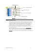
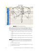

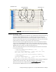
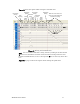


Table Of Contents
- Welcome
- Audience
- Related Documentation
- FTXL Hardware Overview
- FTXL Developer’s Kit Hardware
- FTXL Transceiver Hardware Interface
- FPGA Design for the FTXL Transceiver
- Working with the Altera Development Environments
- Using the Bring-Up Application to Verify FTXL Hardware Design
- Index
FTXL Hardware Guide 77
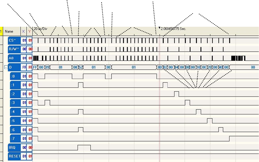
Figure 33 shows the signals while writing the downlink data.
Read Status
(Ready)
Write
Length (9)
Read
Status
(Busy)
Read Status
(Ready)
Write Data
(0x52)
Read
Status
(Busy)
Read Status
(Ready)
Write Data
(0x01)
Read
Status
(Busy)
Read Status
(Ready)
Write 0x02, 0x04, 0x08, 0x10,
0x20, 0x40, 0x80. Read status
between each (ready)
Data bytes
Figure 33. Writing the Downlink Data
Note: You can read the data that is being written by looking at the line labeled
D, but because the D0 line switches it function between being a data line and
being the handshake line, be sure to interpret the D line as data only when A0 is
low.
Figure 34 on page 78 shows the signals while reading the uplink data.