
Hardware Owner's manual
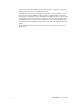

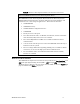
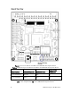
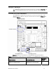
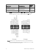
Table Of Contents
- Welcome
- Audience
- Related Documentation
- FTXL Hardware Overview
- FTXL Developer’s Kit Hardware
- FTXL Transceiver Hardware Interface
- FPGA Design for the FTXL Transceiver
- Working with the Altera Development Environments
- Using the Bring-Up Application to Verify FTXL Hardware Design
- Index

12 FTXL Developer’s Kit Hardware
FTXL Function DBC2C20 Function
DBC2C20
Name
Main power Power supply connector P11
FTXL Transceiver Chip I/O 3.3 V I/O Connector P22
FTXL Transceiver Chip I/O 3.3 V I/O Connector P23
Figure 3 shows the connections for the P22 and P23 headers. The names in
parentheses are the Cyclone II pin assignments for the I/O lines. The FTXL
Developer’s Kit does not use pins 8-14 (PIO17-PIO23) on the P22 header.
P22 Header
1412108642
135791113
GND
PIO12 CTS (C19)
PIO14 RTS (C20)
PIO16 TXD (D19)
PIO18 QSPI_DIN (E18)
PIO20 QSPI_CS_MUX0 (E19)
PIO22 QSPI_CS_MUX2 (E20)
EXTVDD3.3
(J17) HRDY PIO13
(H18) RXD PIO15
(H19) QSPI_DOUT PIO17
(F20) QSPI_CLK PIO19
(G20) QSPI_CS_MUX1 PIO21
(G18) A1 PIO23
P23 Header
1412108642
135791113
GND
PIO0 D0 (P15)
PIO2 D2 (F14)
PIO4 D4 (F15)
PIO6 D6 (E18)
PIO8 CS~ (H15)
PIO10 A0 (H14)
EXTVDD3.3
(J14) D1 PIO1
(J15) D3 PIO3
(H17) D5 PIO5
(G17) D7 PIO7
(H16) R/W~ PIO9
(G16) RST PIO11
Figure 3. FTXL Transceiver Chip I/O Header Connections for P22 and P22 Headers
For more information about the pins used for the FTXL Transceiver, see
FTXL
Transceiver Pin Characteristics
on page 24.