
Hardware Owner's manual

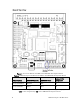
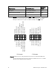
Table Of Contents
- Welcome
- Audience
- Related Documentation
- FTXL Hardware Overview
- FTXL Developer’s Kit Hardware
- FTXL Transceiver Hardware Interface
- FPGA Design for the FTXL Transceiver
- Working with the Altera Development Environments
- Using the Bring-Up Application to Verify FTXL Hardware Design
- Index

10 FTXL Developer’s Kit Hardware
Figure 1. Service Pin Button and LED on the DBC2C20 Development Board
Table 4. FTXL Developer’s Kit Button and LED on the DBC2C20 Development Board
FTXL Function DBC2C20 Function DBC2C20 Name
Cyclone II Pin
Assignment
Service Pin Button Button 0 P25 U1
Service Pin LED LED 4 D17 U8
The FTXL Developer’s Kit does not use the two-digit seven-segment display
(U24) or the navigation key (P2) on the DBC2C20 development board.